Sign In
Upload
Manuals
Brands
Minebea Intec Manuals
Controller
CSD-918B
Minebea Intec CSD-918B Manuals
Manuals and User Guides for Minebea Intec CSD-918B. We have
1
Minebea Intec CSD-918B manual available for free PDF download: Operating Instructions Manual
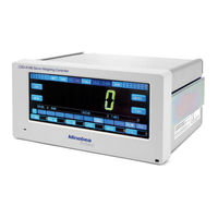
Minebea Intec CSD-918B Operating Instructions Manual (240 pages)
Weight Controller
Brand:
Minebea Intec
| Category:
Controller
| Size: 2 MB
Table of Contents
Table of Contents
3
Introduction
11
Hotline
12
Safety Instructions
13
Installing the Instrument
14
Power Supply
16
Conformed Standards
18
Product Overview
19
Names and Functions of Parts
20
Rear Panel
24
Wiring
25
Wire Connection Cable
26
Connecting Load Cells in Parallel
29
Connection with Power Supply and the Ground
30
Connecting the PULSE F and PULSE R
31
Connecting the Encoder A-Phase Pulse and Encoder B-Phase Pulse
32
Connecting the Input
33
Output Connection
34
Connecting to a 2-Pin Method Serial Interface
35
Operations
37
Variety of Screen
38
The Common Setting Method of each Screen
39
Setting Method by Inputting an Optional Amount
40
Calibration
41
Weighing Calibration Procedure
43
Change to Weighing Calibration Screen
44
SPAN Calibration (SPAN ADJUSTMENT)
46
Fine Adjustment at Zero and SPAN (FINE ADJUSTMENT)
47
Fine Calibration of Zero and SPAN
48
Switch to Registration and Conirmation Screen of Pitch
49
Switch to Digital Linearize Screen
50
CAL-Switch
51
Various Functions Set by the Other Calibration Screen
52
Servo Calibration
55
Procedure of Servo Calibration
56
Maximum Frequency of Input Pulse (MAX. INPUT PULSE FREQ.)
57
Input Pulse Per One Rotation of a Motor (INPUT PULSE/REV.)
58
Input Efective State (INPUT ENABLED STATE)
62
Original Point Sensor Signal (ORIGIN SENSOR)
63
Switch to Calibration Screen of Manual Speed
64
Positional Calibration (POSITION CALIB.)
65
Switch to Position Calibration Screen
66
Manual Operation (MANUAL CONTROL)
69
Movement of Manual Operation
70
Software Limit (SOFTWARE LIMIT)
71
Close Side Software Limit
72
Graphical Display Function (GRAPHIC DISPLAY)
74
Basic Function Setting Display (BASIC FUNCTION)
77
Setting of Stabilization Ilter (STABILIZATION FILTER)
78
Stability Detection
79
Stability Detection Time (STAB. DETECTION TIME)
80
Target of Zero Tracking (TARGET of ZERO TRACKING)
81
Tare Weight Cancellation
82
Read-Out Operation of Preset Tare as Zero (PRESET TARE=0 CHOICE)
83
Power-On Tare Weight Cancellation
84
Accumulation
85
Graph Trigger Level Setting (GRAPH TRIGGER LEVEL)
86
Hold of Weight Display Value (LOAD DISPLAY VALUE HOLD)
87
O Setting (I/O)
88
Setting of External Control I/O
89
Tables of External Control Output Data Function
91
Setting of Servo Control Interface
92
Key Lock
93
Temporary Release Method of Menu Key Lock
94
Switching Method of STANDARD/SIMPLE When the Menu Key Lock Is Efective
95
Weighing Mode
96
Setting Method of Brand Name (NAME)
97
Coarse Low (FULL FLOW)
100
Coarse Low Ixed Open Rate (Weight)
101
Middle Low (MEDIUM FLOW)
102
Middle Low Ixed Open Rate (Weight)
103
Arbitrary Control of Middle Low
104
Fine Low (DRIBBLE FLOW)
105
Switch to Ine Low Screen
106
Prevent Scatter (PREVENT SCATTER)
107
Quadratic Control of Prevent Scatter
108
Batching Mode
109
Sequential Batching Mode
111
Supplementary Batch (Discharge) Mode
114
Nozzle Control Sequence
116
Automatic Free Fall Correction
118
Input of SAFETY CONFIRMATION
119
DISCHARGE Mode
120
Setting Weighing Operation (WEIGHING OPERATION)
121
Setting Item of Weighing Operation
122
Setting Item of Sequence Control (SEQUENCE CONTROL)
124
System Setting (SYSTEM)
129
Operational Check Function (CHECK
130
O Check (CHECK of I/O)
131
Check of Analog Output (ANALOG OUTPUT)
132
Storage Location of Setting Data
133
Pin Method Serial Interface (S-I/F)
134
Explanation of Format Data
135
Standard RS-485 Interface
137
Setting Item of Standard RS-485 Communication
138
Connecting Method
139
Options
141
Connection of Analog Output
142
Selection of Target of Analog Output
143
Analog Output Ine Calibration
144
Switch to BCD Output Setting Screen
145
Pin Assignment of the BCD Output
146
O Equivalent Circuits
148
Output State
150
Operation Mode of RS-232C Interface
151
Pin Assignment of the RS-232C Interface
152
RS-422/485 Interface
154
Switch to RS-422/485 Interface Setting Screen
155
Pin Assignment of the 422/485 Interface
157
RS-232C/422/485 Communication Data Formats
160
Maintenance
187
Troubleshooting
189
Execute Trouble Shooting
190
Error Display and Buzzer Sound
201
Zero Error Display
203
Error Alarm Buzzer
204
Appendix
206
Os
207
Weighing Operations
208
Calibration
209
Built-In Serial I/F
210
Customer Service
211
Display Speciications
212
General Speciications
214
Standard Shipping Speciications
215
RS-232C/422/485 Communication Data Formats
216
Advertisement
Advertisement
Related Products
Minebea Intec CSD-918 Series
Minebea Intec CSD-903
Minebea Intec CSD-903-P07
Minebea Intec CSD-903-P25
Minebea Intec CSD-903-P15
Minebea Intec CAS Series
Minebea Intec CAW Series
Minebea Intec CAISL2
Minebea Intec CAW1P
Minebea Intec CAW2P
Minebea Intec Categories
Scales
Accessories
Cable Box
Racks & Stands
Industrial Equipment
More Minebea Intec Manuals
Login
Sign In
OR
Sign in with Facebook
Sign in with Google
Upload manual
Upload from disk
Upload from URL