Sign In
Upload
Manuals
Brands
Mindray Manuals
Diagnostic Equipment
DP-Z6T
Mindray DP-Z6T Manuals
Manuals and User Guides for Mindray DP-Z6T. We have
1
Mindray DP-Z6T manual available for free PDF download: Service Manual
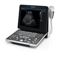
Mindray DP-Z6T Service Manual (187 pages)
Diagnostic Ultrasound System
Brand:
Mindray
| Category:
Diagnostic Equipment
| Size: 12 MB
Table of Contents
Table of Contents
3
Table of Content
7
Revision History
7
Intellectual Property Statement
8
Applicable for
8
Statement
9
Responsibility on the Manufacturer Party
9
Customer Service Department
9
Preface
11
Meaning of Signal Words
11
Meaning of Symbols
11
Meaning of Safety Symbols
11
Warning Labels
12
General Symbols
12
Safety Precautions
14
Electric Safety
14
Mechanical Safety
15
Personnel Safety
15
Other
15
Product Specifications
17
Overview
17
Intended Use
17
Introduction of each Unit
17
I/O Panel
20
Power Supply Panel
20
Control Panel
21
Peripherals Supported
24
Specifications
24
Dimensions and Weight
24
Electrical Specifications
24
Environmental Conditions
24
Monitor Specification
25
System Installation
27
Preparations for Installation
27
Electrical Requirements
27
Installation Condition
28
Unpacking
28
Unpacking
29
Checking
31
Installation of Main Unit
31
Installing Battery
31
Control Panel Adjusting
31
Display Adjusting
32
Installing Probe Holder
33
Connecting a Probe
33
Installing Peripherals
34
Footswitch Installation
34
Video Printer Installation
34
Installing a Graph / Text Printer
35
Installing Printer Adapter
36
Installing External DVD-R/W
40
System Configuration
40
Power on / off
40
Enter Doppler
40
System Preset
41
Print Preset
44
Network Preset
46
System Information
49
Hardware Principle
51
General Structure of Hardware System
51
Main Unit
52
Probe Board
52
Main Board
54
IO Broad
56
Drive Board (Optional)
57
Ultrasound System Monitor
57
Ultrasound System Indicator
58
Display
59
Control Panel
60
Power System
61
Power Output of the Power Supply Module and Supporting Function Distribution
61
System Power-On Control
62
Function and Performance Checking Method
65
Instruction
65
Checking System Status
65
System Running Status
65
General Exam
66
Check Flow
66
Checking Content
66
Function Checks
68
Check Flow
69
Checking Content
69
Performance Test
76
Test Process
76
Test Content
76
Software Upgrade and Maintenance
83
Enter the Maintenance Window
83
System Software Installation/ Restoration
84
Installation of Optional Devices
84
Data Backup and Storage
87
Manage Settings
87
Patient Data Backup and Restore
88
Software Maintenance
89
Product Configuration
89
Log Maintenance
89
Display Parameter Setting
91
HDD Partition
92
Field Replacement Unit
95
Explosive View
96
Assembly Explosive View
97
Monitor Assembly (A0)
97
Operation Panel Assembly (B0)
98
Core Assembly (C0)
101
Cable Set of Main Unit (D0)
107
Mobile Trolley(E0
109
Structure and Assembly/Disassembly
111
Structure of the Complete System
111
Preparations
111
Tools Required
111
Engineers Required
112
Assembly/Disassembly Required
112
Assembly/Disassembly
112
Battery Connecting Board
113
Power Supply Module
114
IO Broad
118
Probe Board
119
Main Board and CPU Module
120
Control Panel Assembly
122
Display Assembly
126
Hard Disk
127
Speaker
128
Printer Adapter (Optional)
130
System Diagnosis and Support
133
General Status Indicator
133
Status Indicators of the Control Panel
133
Status Indicator of the Power Supply on the IO Board
134
Status of Whole Machine
134
Starting Process of the Whole System
135
Start Process of Complete System
136
Start-Up Process of BIOS
137
Start-Up of Linux
137
Start-Up of Doppler
138
Alarming and Abnormal Information
140
Turning on the System Configuration File Is Abnormal
141
The Voltage of System Power Is Abnormal
141
Temperature Alarming
141
Fan Alarming
142
Battery Alarming
142
PHV Related Alarming
143
Care and Maintenance
145
Overview
145
Tools, Measurement Devices and Consumables
145
Care and Maintenance Items
146
Cleaning
147
Clean the System
147
Clean the Peripherals
150
Checking
150
General Check
150
System Function Check
151
Peripherals and Options Check
152
Mechanical Safety Inspection
152
Electrical Safety Inspection
153
Troubleshooting of Regular Malfunctions
155
System Cannot be Powered on
155
Module or Board Related
155
Key Points Supporting Troubleshooting
155
Troubleshooting
155
System Cannot Start up Normally
156
Module or Board Related
156
Key Points Supporting Troubleshooting
156
Troubleshooting
156
Image Fault
157
Module or Board Related
157
Key Points Supporting Troubleshooting
158
Troubleshooting
158
Probe Socket System Malfunction
159
Module or Board Related
159
Key Points Supporting Troubleshooting
159
Troubleshooting
159
IO Interface System
160
Module or Board Related
160
Key Points Supporting Troubleshooting
160
Troubleshooting
160
Control Panel
161
Module or Board Related
161
Key Points Supporting Troubleshooting
161
Troubleshooting
161
LCD Display
162
Module or Board Related
162
Key Points Supporting Troubleshooting
162
Troubleshooting
162
Printer Adapter Related Troubleshooting
164
Electrical Safety Inspection
167
Appendix A ELECTRICAL SAFETY INSPECTION
183
Appendix B Phantom Usage Illustration
183
Advertisement
Advertisement
Related Products
Mindray DP-Z6
Mindray DP-Z6S
Mindray DP-Z60
Mindray DP-Z60S
Mindray DP-Z60W
Mindray DP-Z60 Pro
Mindray DP-Z6 Vet
Mindray DP-Z60 Vet
Mindray DP-Z60T
Mindray DP-Z6 Pro
Mindray Categories
Medical Equipment
Diagnostic Equipment
Measuring Instruments
Monitor
Water Pump
More Mindray Manuals
Login
Sign In
OR
Sign in with Facebook
Sign in with Google
Upload manual
Upload from disk
Upload from URL