Sign In
Upload
Manuals
Brands
Miller Electric Manuals
Inverter
CBI 801D
Miller Electric CBI 801D Manuals
Manuals and User Guides for Miller Electric CBI 801D. We have
1
Miller Electric CBI 801D manual available for free PDF download: Owner's Manual
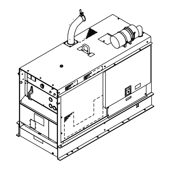
Miller Electric CBI 801D Owner's Manual (56 pages)
Engine Driven Welding Generator
Brand:
Miller Electric
| Category:
Inverter
| Size: 1 MB
Table of Contents
Table of Contents
4
Section 1 − Safety Rules for Operation of Arc Welding Power Source
6
Introduction
6
General Precautions
6
Arc Welding
9
Standards Booklet Index
10
Section 2 − Safety Precautions and Signal Words
11
General Information and Safety
11
Safety Alert Symbol and Signal Words
11
Section 3 − Specifications
12
Duty Cycle
13
Volt-Ampere Curves
13
Description
13
Section 4 − Installation or Relocation
13
Location
13
Chart 3-1. Volt-Ampere Curves
13
Chart 3-2. Air Output Curve
13
Exhaust Extension Installation
14
Connecting the Battery
14
Fuel
15
Lubrication
15
Equipment Grounding Terminal
15
Chart 4-1. Fuel Consumption Curve
15
Weld Output Connections
16
Table 4-1. Weld Cable Size
16
Remote Control Connections
17
Air Compressor Connections
19
Ether Starting Aid (Optional)
19
Section 5 − Auxiliary Power
20
General
20
120 Volt Terminals
20
Chart 5-1. AC Power Curve for 120 Volt Terminals
20
Section 6 − Operator Controls
21
Ampere Ranges Switch
21
Amperage & Voltage Adjustment Control
21
Engine Control Switch
21
Remote Amperage & Voltage Control Switch
22
Output(Contactor) Switch
22
Service Engine Air Cleaner Light
22
Check Alternator
22
Hour Meter
22
Fuel Gauge
23
6-10. Magnetic Shutdown Switch
23
Oil Temperature Gauge/Switch
23
Oil Pressure Gauge/Switch
23
Battery Gauge
23
Meters
23
Broken Cooling Belt Shutdown Switch
23
Ether Starting Aid (Optional)
23
Section 7 − Sequence of Operation
24
Shielded Metal Arc Welding (SMAW)
24
Gas Metal Arc (GMAW) and Flux Cored Arc Welding (FCAW)
24
Table 7-1. Suggested Electrode Diameter for Amperage Range (CAC-A Only)
25
Air Carbon Arc Cutting and Gouging (CAC-A)
25
Auxiliary Power Operation
25
Air Compressor Operation
25
Starting the Engine
25
Table 7-2. Flow of Free Air (CFM) through Orifices of Various Diameters
26
Stopping the Engine
26
Table 8-1. Maintenance Schedule
28
Section 8 − Maintenance
28
Routine Maintenance
28
Table 8-2. Air Cleaner Service
30
Air Cleaner Service
30
Fuel/Water Separator and Sludge Drain Plug
31
Fuel Filter
31
Battery Replacement Procedure
31
Maintenance-Free Battery Charging
32
Governor
32
Engine Speed Adjustments
32
Brushes and Slip Rings
33
Ether Starting Aid (Optional)
33
8-11. Spark Arrestor
33
8-12. Run-In Procedure
34
Diagram 8-1. Load Bank Connections
35
Diagram 8-2. Resistance Grid Connections
36
Section 9 − Troubleshooting
36
General
36
Booster Battery Jump Starting
36
Overload Protection
37
Circuit Board Handling Precautions
37
Table 9-1. Weld/Power Troubleshooting
38
Troubleshooting
38
Table 9-2. Auxiliary Power Troubleshooting
39
Table 9-4. Air Compressor Troubleshooting
39
Table 9-3. Engine Troubleshooting
39
Section 10 − Electrical Diagrams
41
Diagram 10-1. Circuit Diagram for Welding Generator
41
SECTION 11 − PARTS LIST Figure 11-1A. Main Assembly
43
Advertisement
Advertisement
Related Products
Miller Electric CP-202
Miller Electric CP-302
Miller Electric CP-252TS
Miller Electric CST 250 VRD International
Miller Electric CST 250
Miller Electric Gas Cylinder Rack
Miller Electric Coolmate 3.5
Miller Electric CE-60TM
Miller Electric CP-750E
Miller Electric Blue Star 145
Miller Electric Categories
Welding System
Welding Accessories
Inverter
Controller
Utility Vehicle
More Miller Electric Manuals
Login
Sign In
OR
Sign in with Facebook
Sign in with Google
Upload manual
Upload from disk
Upload from URL