Sign In
Upload
Manuals
Brands
Metronix Manuals
Servo Drives
ARS 2305 SE
Metronix ARS 2305 SE Manuals
Manuals and User Guides for Metronix ARS 2305 SE. We have
2
Metronix ARS 2305 SE manuals available for free PDF download: Product Manual
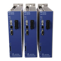
Metronix ARS 2305 SE Product Manual (154 pages)
Brand:
Metronix
| Category:
Servo Drives
| Size: 1 MB
Table of Contents
Table of Contents
4
1 General
12
Documentation
12
Scope of Supply
13
Table 1: Scope of Supply ARS 2300 SE with STO
13
Table 2: Scope of Supply ARS 2300 SE Without STO
13
Table 3: Connector Set: POWER Connector
13
2 Safety Notes for Electrical Drives and Controllers
15
Symbols
15
General Notes
16
Hazards Resulting from Misuse
18
Safety Instructions
19
General Safety Instructions
19
Safety Notes for Assembly and Maintenance
21
Protection against Contact with Electrical Parts
23
Protection against Electric Shock by Way of Protective Extra-Low Voltage (PELV)
24
Protection against Dangerous Movements
25
Protection against Contact with Hot Parts
26
Protection During the Handling and Installation of the Devices
27
3 Product Description
28
General
28
Figure 1: Type Key
28
Power Supply
31
Three-Phase AC Power Supply
31
DC Bus Circuit Linking, DC Supply
31
Mains Fuse
31
Brake Chopper
32
Communication Interfaces
32
USB Interface [X19]
32
UDP Interface [X18]
33
CAN Interface [X4]
33
I/O Functions and Device Control
33
4 Technical Data
35
General Technical Data
35
Control Elements and Display Elements
36
Table 8: Technical Data: Cable Specifications
36
Table 9: Technical Data: Motor Temperature Monitoring System
36
Table 10: Display Elements and RESET Button
36
Power Supply [X9]
37
Table 11: Technical Data: Power Data [X9]
37
Table 12: Technical Data: Internal Braking Resistor [X9]
37
Table 13: Technical Data: External Braking Resistor [X9]
37
Motor Connector [X6]
38
Current Derating
38
Table 14: Technical Data: Motor Connector [X6]
38
Table 15: ARS 2302 SE: Rated Current Values for an Ambient Temperature 40°C
40
Table 16: ARS 2305 SE: Rated Current Values for a Blocked or Slow-Running Motor
40
Table 17: ARS 2305 SE: Rated Current Values for a Rotating Motor
41
Table 18: ARS 2310 SE: Rated Current Values for a Blocked or Slow-Running Motor
41
Table 19: ARS 2310 SE: Rated Current Values for a Rotating Motor
42
Angle Encoder Connector [X2A] and [X2B]
43
Resolver Connector [X2A]
43
Table 20: Technical Data: Resolver [X2A]
43
Encoder Connector [X2B]
44
Table 21: Technical Data: Resolver Interface [X2A]
44
Table 22: Technical Data: Encoder Evaluation [X2B]
44
Communication Interfaces
46
Usb [X19]
46
Ethernet [X18]
46
CAN Bus [X4]
46
SD/SDHC/MMC Card
46
Table 23: Technical Data: USB [X19]
46
Table 24: Technical Data: Ethernet [X18]
46
Table 25: Technical Data: CAN Bus [X4]
46
Table 26: Technical Data: SD/SDHC/MMC Card
46
I/O Interface [X1]
47
Incremental Encoder Input [X10]
48
Table 28: Technical Data: Analogue Inputs and Outputs [X1]
48
Table 29: Technical Data: Incremental Encoder Input [X10]
48
Incremental Encoder Output [X11]
49
Table 30: Technical Data: Incremental Encoder Output [X11]
49
5 Function Overview
50
Motors
50
Synchronous Servomotors
50
Linear Motors
50
Functions of the ARS 2300 SE Servo Drives
51
Compatibility
51
Pulse Width Modulation (PWM)
51
Figure 2: Control Structure of the ARS 2300 SE
51
Setpoint Management
53
Torque-Controlled Mode
53
Speed-Controlled Mode
53
Torque-Limited Speed Control
54
Synchronisation with External Clock Signals
54
Load Torque Compensation in the Case of Vertical Axes
54
Positioning and Position Control
54
Synchronisation, Electronic Gear Unit
55
Brake Management
55
Contouring Control with Linear Interpolation
56
Time-Synchronised Multi-Axis Positioning
56
Figure 3: Linear Interpolation between Two Data Values
56
Electronic Cam Discs
58
Positioning Control
59
Overview
59
Relative Positioning
60
Absolute Positioning
60
Motion Profile Generator
60
Figure 4: Motion Profiles of the ARS 2300 SE Servo Drive
60
Homing
61
Positioning Sequences (Path Program)
61
Figure 5: Path Program
61
Optional Stop Input
62
Jogging Mode and Teach-In Mode
62
6 Functional Safety Technology
63
General
63
Description of the Integrated Safety Function STO
63
Figure 6: Schematic Representation of the Integrated Safety Function STO
64
7 Mechanical Installation
65
Important Notes
65
Installation Space and Mounting Clearance
66
Figure 7: Servo Drive ARS 2310 SE with and Without STO: Installation Space and Mounting Clearance
66
Device View
67
Figure 8: Servo Drive ARS 2310 SE: Front View
67
Figure 9: Servo Drive ARS 2302 SE: View from above
68
Figure 10: Servo Drive ARS 2302 SE: View from below
68
Installation
69
8 Electrical Installation
70
Connector Configuration
70
Figure 12: Connection to the Power Supply [X9] and Motor [X6]
70
ARS 2300 SE - Complete System
72
Figure 13: Complete Set-Up of the ARS 2300 SE (Example with STO) with a Motor and PC
73
Connector: Power Supply [X9]
74
Configuration on the Device [X9]
74
Mating Connector [X9]
74
Pin Assignment [X9]
75
Cable Type and Configuration [X9]
75
Table 32: Pin Assignment [X9]
75
Connection Notes [X9]
76
Figure 14: Power Supply [X9]
76
Table 33: Pin-And-Socket Connector [X9]: External Braking Resistor
76
Connector: Motor [X6]
77
Configuration on the Device [X6]
77
Mating Connector [X6]
77
Pin Assignment [X6]
77
Cable Type and Configuration [X6]
78
Connection Notes [X6]
79
Figure 15: Motor Connector [X6]
79
Figure 16: Connecting a Locking Brake with a High Current Demand (> 2 A) to the Device
80
Connector: I/O Communication [X1]
81
Figure 17: Basic Circuit Diagram of Connector [X1]
82
Configuration on the Device [X1]
83
Mating Connector [X1]
83
Pin Assignment [X1]
84
Table 35: Pin Assignment: I/O Communication [X1]
84
Cable Type and Configuration [X1]
85
Connection Notes [X1]
85
Connector: Resolver [X2A]
86
Configuration on the Device [X2A]
86
Mating Connector [X2A]
86
Pin Assignment [X2A]
86
Table 36: Pin Assignment: [X2A]
86
Cable Type and Configuration [X2A]
87
Connection Notes [X2A]
87
Figure 18: Pin Assignment: Resolver Connector [X2A]
87
Connector: Encoder [X2B]
89
Configuration on the Device [X2B]
89
Mating Connector [X2B]
89
Table 37: Pin Assignment: Analogue Incremental Encoder [X2B]
90
Table 38: Pin Assignment: Incremental Encoder with Serial Interface (E.g. Endat, HIPERFACE ® ) [X2B]
91
Cable Type and Configuration [X2B]
92
Connection Notes [X2B]
93
Figure 19: Pin Assignment: Analogue Incremental Encoder [X2B]
93
Figure 20: Metronix Servocommander : Angle Encoder Settings [X2B]
93
Figure 21: Pin Assignment: Incremental Encoder with a Serial Interface
94
Figure 22: Pin Assignment: Digital Incremental Encoder [X2B]
95
Connector: Incremental Encoder Input [X10]
96
Configuration on the Device [X10]
96
Mating Connector [X10]
96
Pin Assignment [X10]
96
Table 40: Pin Assignment: Incremental Encoder Input [X10]
96
Cable Type and Configuration [X10]
97
Connection Notes [X10]
97
Figure 23: Pin Assignment: Incremental Encoder Input [X10]
97
Connector: Incremental Encoder Output [X11]
98
Configuration on the Device [X11]
98
Mating Connector [X11]
98
Pin Assignment [X11]
98
Table 41: Pin Assignment: Incremental Encoder Output [X11]
98
Cable Type and Configuration [X11]
99
Connection Notes [X11]
99
Figure 24: Pin Assignment: Incremental Encoder Output [X11]
99
Connector: CAN Bus [X4]
100
Configuration on the Device [X4]
100
Mating Connector [X4]
100
Pin Assignment [X4]
100
Table 42: Pin Assignment: CAN Bus [X4]
100
Cable Type and Configuration [X4]
101
Connection Notes [X4]
101
Figure 25: CAN Bus Cabling Example
101
Figure 26: Integrated CAN Terminating Resistor
102
Connector: USB [X19]
103
Configuration on the Device [X19]
103
Mating Connector [X19]
103
Pin Assignment USB [X19]
103
Cable Type and Configuration [X19]
103
Figure 27: Pin Assignment: USB Interface [X19], Front View
103
Table 43: Pin Assignment: USB Interface [X19]
103
Connector [X40]
104
SD/SDHC/MMC Card
104
Supported Card Types
104
Supported Functions
104
Supported File Systems
104
File Names
104
Pin Assignment SD/SDHC/MMC Card
105
Figure 28: Pin Assignment: SD/MMC Card
105
Table 44: Pin Assignment: SD and SDHC Card
105
Table 45: Pin Assignment: MMC Card
105
BOOT-DIP Switch
106
Notes Concerning the Safe and EMC-Compliant Installation
107
Definitions and Terms
107
General Information on EMC
107
EMC Areas: First and Second Environment
108
EMC-Compliant Cabling
109
Operation with Long Motor Cables
110
ESD Protection
110
9 Additional Requirements to be Fulfilled by the Servo Drives for Ul Approval
111
Mains Fuse
111
Wiring Requirements and Environmental Conditions
111
Motor Temperature Sensor
111
10 Start-Up
112
General Connection Notes
112
Tools/Material
112
Connecting the Motor
112
Connecting the ARS 2300 SE Servo Drive to the Power Supply
113
Connecting the PC (USB Interface)
113
Operability Check
113
11 Service Functions and Error Messages
114
Protection and Service Functions
114
Overview
114
Phase and Mains Power Failure Detection
114
Overcurrent and Short-Circuit Monitoring
114
Overvoltage Monitoring of the DC Bus Circuit
115
Temperature Monitoring of the Heat Sink
115
Monitoring of the Motor
115
I²T Monitoring
115
Power Monitoring of the Brake Chopper
115
Start-Up Status
116
Rapid Discharge of the DC Bus Circuit
116
Operating Hours Counter
116
Operating Mode and Error Messages
117
Operating Mode and Error Indication
117
Table 47: Operating Mode and Error Indication
117
Error Messages
118
Table 48: Error Messages
118
Advertisement
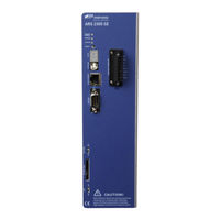
Metronix ARS 2305 SE Product Manual (54 pages)
STO (Safe Torque Off) for the servo drives
Brand:
Metronix
| Category:
Servo Drives
| Size: 1 MB
Table of Contents
Other Symbols
5
Table of Contents
6
Product Identification
11
Table 1: Documentation on the Servo Drives ARS 2000 SE
12
Safety and Requirements for Product Use
13
Safety
13
General Safety Information
13
Intended Use
14
Possible Incorrect Application
14
Iso 13849-1 / en 61800-5-2
15
Requirements for Product Use
15
Technical Requirements
15
Qualification of the Specialist Personnel (Requirements for Personnel)
15
Diagnostic Coverage (DC)
16
Range of Applications and Certification
16
Product Description Ars 2000 Se with Integrated Sto Function
17
Product Overview
17
Purpose
17
Supported Devices
17
Table 2: Overview ARS 2000 SE Series of Devices with Integrated STO Function
17
Connections
18
Function and Application
18
Figure 1: Connections of the ARS 2000 SE for the STO Function
18
Description of the Safety Function STO
19
Figure 2: "Safe Torque Off" - Operating Principle for the ARS 2000 SE
19
Overview of Interface [X40]
20
Connections Description
21
Table 3: Function of the Servo Drive Connections
21
Control Ports STO-A, 0V-A / STO-B, 0V-B [X40]
21
Section 3.2.3, Figure
21
2.2.3.1 Discrepancy Time
22
2.2.3.2 Test Pulse
22
Feedback Contact C1, C2 [X40]
22
Auxiliary Supply 24V, 0V [X40]
23
Functionalities in the Servo Drive ARS 2000 SE
23
Table 4: Detection and Response Times of the Driver Supply Voltage
25
Time Behaviour
26
Basic Time Behaviour STO
26
Figure 3: Basic Time Behaviour When Activating and Deactivating the Safety Function STO
26
Table 5: Time Data Concerning Figure 3
26
Time Behaviour for Activating STO During Operation with Restart
27
Figure 4: Time Behaviour When Activating the Safety Function STO with Restart
27
Table 6: Time Data Concerning Figure 4
28
Time Behaviour for Activating SS1 During Operation with Restart
29
Figure 5: Time Behaviour When Activating the Safety Function SS1 (External Switching) with Restart
29
Table 7: Time Data Concerning Figure 5
30
Assembly and Installation
31
Mounting / Dismounting
31
Electrical Installation
31
Safety Instructions
31
ESD Protection
31
Connection [X40]
32
Table 8: Pin Assignment [X40]
32
Minimum Wiring for Commissioning [X40]
32
Value Description
32
Typical Circuits
33
Safe Torque off (STO)
33
Figure 6: Connection of the Integrated STO Function, Example of Single-Phase Servo Drive ARS 2000 SE
33
Delays and Safe Torque Switch off (SS1, "Safe Stop 1")
34
Figure 7: Typical Circuit "Decelerate and Safe Torque Off" (SS1, "Safe Stop 1"), Example Single-Phase Servo Drive ARS 2000 SE
34
Commissioning
36
Before Commissioning
36
Parameterisation with Metronix Servocommander
37
Figure 8: Type Indication of the Safety Function and Extended Status Window
37
Type Indication Servo Drive and Safety Function
38
Status Indication of the State Machine
38
Window "Safety Module (Integrated)
38
Figure 9: Quick-Access Toolbar with the Button "Safety
38
4.2.3.1 Info
39
Figure 10: Window "Safety Module (Integrated)
39
4.2.3.2 Status-Leds of the State Machine
40
Table 9: Meaning of the Leds for the Status Display in the Window "Safety Module (Integrated)
40
Function Test, Validation
41
Table 10: Questions for Validation in Accordance with en ISO 12100-1:2010 (Example)
41
Table 11: Questions for Validation in Accordance with en ISO 13849-1 and -2 (Example)
42
Operation
43
Obligations of the Operator
43
Maintenance and Care
43
Protective Functions
43
Voltage Monitoring
43
Protection against Overvoltage and Reverse Polarity
43
Diagnostics and Troubleshooting
44
Display on the Servo Drive
44
Error Messages
44
Table 12: Seven Segment Display on the Servo Drive
44
Table 13: Error Messages Relating to the Integrated STO Circuit
45
Conversion
46
Repair and Replacement of the Integrated STO Circuit
46
Replacing the Previous Series ARS 2000 with the ARS 2000 SE
46
Ars 2000
46
Ars 2000 Se
46
Modifications to the Connection Wiring
46
Information for Configuration
47
Technical Appendix
48
Technical Data
48
Safety Engineering
48
Table 14: Technical Data: Safety Indicators
48
General
49
Table 15: Technical Data: Safety Specifications
49
Table 16: Technical Data: Certification
49
Operating and Environmental Conditions
50
Table 17: Technical Data: Ambient Conditions and Qualification
50
Electrical Data
51
Table 18: Technical Data: Electrical for Ports STO-A and STO-B
51
Table 19: Typical Switch-Off Time and Minimum Tolerance Time for Test Pulse (OSSD Signals)
51
Table 20: Technical Data: Electrical Data of the Feedback Contact C1/C2
52
Table 21: Technical Data: Electrical Data of the Auxiliary Supply Output
52
Table 22: Technical Data: Electrical Isolation [X40]
52
Table 23: Technical Data: Cabling to [X40]
53
Glossary
54
Table 24: Terms and Abbreviations
54
Advertisement
Related Products
Metronix ARS 2320 FS
Metronix ARS 2340 FS
Metronix ARS 2360W FS
Metronix ARS 2300 SE
Metronix ARS 2320
Metronix ARS 2340
Metronix ARS 2320W
Metronix ARS 2360W
Metronix ARS 2302 SE
Metronix ARS 2310 SE
Metronix Categories
Servo Drives
Controller
More Metronix Manuals
Login
Sign In
OR
Sign in with Facebook
Sign in with Google
Upload manual
Upload from disk
Upload from URL