Sign In
Upload
Manuals
Brands
Metrohm Manuals
Laboratory Equipment
761 Compact IC
Metrohm 761 Compact IC System Manuals
Manuals and User Guides for Metrohm 761 Compact IC System. We have
1
Metrohm 761 Compact IC System manual available for free PDF download: Instructions For Use Manual
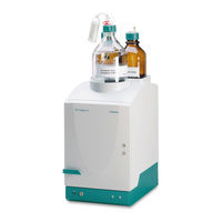
Metrohm 761 Compact IC Instructions For Use Manual (228 pages)
Compact Ion Chromatography Analyzer
Brand:
Metrohm
| Category:
Laboratory Equipment
| Size: 3 MB
Table of Contents
Table of Contents
3
Introduction
11
Instrument Description
11
Parts and Controls
13
Fig. 1: Front of the 761 Compact IC
13
Fig. 2: Rear of the 761 Compact IC
14
Opening for Detector Cable 5
15
Fig. 3: Interior of the 2.761.0010 Compact IC
16
Fig. 4: Interior of the 2.761.0020 Compact IC
18
Information on the Instructions for Use
20
Organization
20
Notation and Pictograms
21
Safety Notes
22
Electrical Safety
22
General Precautionary Rules
22
Installation
23
Overview
23
Flow Chart
23
Connections in the 761 Compact IC
23
Fig. 5: Connecting Diagram for 2.761.0010 Compact IC Without Suppressor
24
Fig. 6: Connecting Diagram for 2.761.0020 Compact IC with Suppressor
24
Setting up the Instrument
25
Packaging
25
Check
25
Location
25
Attaching the Accessories
25
Connection of Detector Block
25
Connection of Syringe and Aspirating Tubing
26
Connection of the Drain Tube for the Inner Compartment
26
Connection of the Drain Tube for Bottle Rack
27
Connection of PEEK Capillaries
27
Fig. 7: Connectors for Capillaries
27
Filter Unit PEEK
28
Fig. 8: 6.2821.000 Filter Unit PEEK
28
Mains Connection
29
Setting the Mains Voltage
29
Fuses
30
Mains Cable and Mains Connection
30
On/Off Switching of the Instrument
30
Fig. 9: Setting the Mains Voltage
30
Connection to the PC
31
Connecting Cable
31
Software Installation
31
Basic Settings
32
High-Pressure Pump
35
Removing the Transport Security Screws
35
Installing the Pulsation Dampener
35
Fig. 10: Connection of the Pulsation Dampener
36
Connecting the Eluent Bottle
37
Fig. 11: Connection of Eluent Bottle
38
Deaerating the Pump and Rinsing the Pulsation Dampener
39
Column Connection
40
Precolumns and Separating Columns
41
General Information on Precolumns
41
Precolumns with Cartridge Head
41
Manufit Pressure Screw
41
Separating Column
41
Fig. 12: Installation of Precolumn Cartridges with Cartridge Head
42
Precolumn Glass Cartridges with Cartridge Holder
43
IC Anion Precolumn SUPERSEP
44
Fig. 13: Installation of Precolumn Glass Cartridges with Cartridge Holder
44
End Fitting
44
Screw Cap for Precolumn
44
Sleeve for Precolumn Cartridge
44
Precolumn Cartridge
44
Connection Piece
44
Screw Cap for Column
44
General Information on Separating Columns
45
Selection of the Sample Loop
45
Installation of the Separating Column Without Suppressor
46
Installation of the Separating Column with Suppressor
47
Fig. 14: Installation of Column Without Suppressor
47
Suppressor Module
48
General Information on Suppressor Module
48
Preparation of the Peristaltic Pump
48
Fig. 15: Installing Pump Tubings
49
Fig. 16: Connection of the Separating Column with Suppressor
50
Column Holder
50
Aspirating Tubing for H
50
Aspirating Tubing for HSO
50
Coupling
50
Pump Tubing for H 2 so
50
Pump Tubing for HSO
50
6.1803.020 PTFE Tubing
50
Connection of Supply Bottles
51
Suppressor Inlet Capillary for Eluent
51
Suppressor Outlet Capillary for Eluent
51
Suppressor Inlet Capillary for H O
51
Fig. 17: Connection of Supply Bottles
52
Connection of the Suppressor Module
53
Fig. 18: Connections at Suppressor Module
53
Suppressor Inlet Capillary for H 2 so
53
Suppressor Inlet Capillary for HSO
53
Suppressor Outlet Capillary for H O
53
Suppressor Outlet Capillary for H 2 so
53
Suppressor Outlet Capillary for HSO
53
Putting into Operation
55
Putting into Operation Without Suppressor
55
Putting into Operation with Suppressor
56
Connection of External Devices
59
Connection of the 750 Autosampler
59
Connection of the 766 IC Sample Processor
60
Connection of Other Devices
62
Operating Tutorial
63
Requirements
63
Preparations
64
Calibration
65
Sample Determination
73
Operation
77
Fundamentals of the Operation
77
Starting/Closing the Program
77
Glossary
78
Overview of Program Windows
79
Main Window Elements
80
Icons of the Main Window
80
Overview of File Types
81
Context Sensitive Menus
82
Keyboard and Mouse Functions
82
Help
83
Instrument and Software Settings
84
Fonts
84
Security System
84
Global Settings
85
COM Port
87
Systems
88
System Window
88
System File Handling
88
System Functions
89
Connect and Disconnect System
89
Start/Stop Hardware and Record Baseline
89
Start/Stop Determinations
90
Options for Determinations
90
System Settings
92
Modify System Window
92
Watch Window Display
92
Set Start Mode
92
Print System Parameters
93
PC Icon
93
Menu Options for PC Icon
93
Select Processing Method and Data Source
93
Watch Window
94
Menu Options for Screen Icon
94
Instrument Icon
95
Menu Options for Instrument Icon
95
System Parameters for Disconnected System
95
Instrument Control for Connected System
96
Time Program
98
Configuration
100
Hardware Settings
101
Timer
104
System State Window
105
Status Messages
105
Error Messages
106
Methods
107
Method File Handling
107
Passport
107
General
108
Sample
109
Column
110
Eluent
111
Comment
111
Method Log
112
Data Log
113
Method Setup
114
General
114
Measure
114
Filters
115
Processing
116
Math
117
Integration
119
Setup
120
Events
122
Calibration and Quantification
127
General Information
127
Notations
128
External Standard Calibration
129
Component Table
129
Peak Identification
131
Concentration Table
133
Calibration Curve
135
Update Calibration
137
Load and Save Calibration Data
138
Import and Export Calibration Data
138
Put out Calibration Curves
138
Report Output
139
Report Options
139
Chromatograms
151
Chromatogram Window
151
Chromatogram File Handling
152
Open Chromatogram
152
Save Chromatogram
153
Close Chromatogram
153
Delete Chromatogram
153
Export Chromatogram
153
Import Chromatogram
154
Graphical Representation
155
Appearance
155
Other Graphical Functions
159
Peak Editor
160
Switching On/Off the Peak Editor
160
Peak Editor Functions
160
Moving the Cursor
161
Printing
162
Page Layout for Printing
162
Printer Settings
163
Print Preview
163
Printing
163
Miscellaneous Functions
163
Reintegration
163
Recalibration
163
Subtraction of a Chromatogram
164
Data Compression
164
Invert Chromatogram
164
Autodatabase Options
165
Indicate Active Autodatabase Program
165
Sample Queue
166
Sample Queue File Handling
166
Open Sample Queue
166
Save Sample Queue
166
Delete Sample Queue
166
Sample Queue Control
167
Sample Queue Overview Table
167
Start Sample Queue
168
Pause Sample Queue
169
Cancel Last Run
169
Reset Sample Queue
169
Sample Queue Editor
169
Open Queue Editor Window
169
Sample Queue Editor Functions
171
Print Sample Queue
171
Close Sample Queue Editor
171
Batch Reprocessing
172
Batch Reprocessing Queue File Handling
172
Open Batch Reprocessing Queue
172
Create New Batch Reprocessing Queue
172
Save Batch Reprocessing Queue
172
Perform Batch Reprocessing
173
Reprocess Options Window
173
Merge Chromatograms
176
Batch Reprocessing Queue Editor
177
Open Batch Reprocessing Queue Editor Window
177
Batch Reprocessing Queue Editor Functions
178
Print Batch Reprocessing Queue
178
Close Batch Reprocessing Queue Editor
178
Notes - Maintenance - Faults
179
Practical Notes on Ion Chromatography
179
Separating Columns
179
High-Pressure Pump
180
Eluents
181
Peristaltic Pump
181
Suppressor Module
182
Connections
182
Maintenance and Servicing
183
General Information
183
Passivation
183
Recycling
184
Shutdown
184
Changing Separating Columns
184
Maintenance Work at the Pump Head
186
Fig. 19: Components of the Pump Head
187
Fig. 20: Replacement of the Piston Seal 112
187
Fig. 21: Components of Inlet Valve 113 and Outlet Valve 114
189
Regeneration of the Suppressor Module
190
Cleaning the Suppressor
191
Replacing the Suppressor
193
Fig. 22: Assembling the Suppressor
193
Exchanging the Pump Tubing
195
Faults and Malfunctions
196
Error Messages
196
Malfunctions and Their Rectification
196
Diagnostic Tests / Validation / GLP
198
Appendix
199
Technical Data
199
6.1.1 Conductivity Measurement
199
6.1.2 Conductivity Detector
199
6.1.3 Injection Valve
200
6.1.4 High-Pressure Pump
200
6.1.5 Peristaltic Pump
201
6.1.6 Suppressor Module
201
6.1.7 Leak Detector
201
6.1.8 RS232 Interface
201
Remote Interface
202
Analog Output
202
Mains Connection
202
Safety Specifications
202
Electromagnetic Compatibility (EMC)
203
Ambient Temperature
203
Housing
203
Standard Equipment
204
Optional Accessories
208
Accessories for Capillary Connections
208
High-Pressure Pump
209
Separating Columns and Precolumns
210
Additional Devices and Cables
215
Warranty and Conformity
216
Warranty
216
EU Declaration of Conformity
217
Certificate of Conformity and System Validation
218
Index
219
Advertisement
Advertisement
Related Products
Metrohm 768 KF Oven
Metrohm 763 PVC Thermomat
Metrohm 762 IC Interface
Metrohm 761 SD Compact IC
Metrohm 760
Metrohm 736 GP Titrino
Metrohm 726
Metrohm 793 IC
Metrohm 774
Metrohm Titrino 719 S
Metrohm Categories
Laboratory Equipment
Measuring Instruments
Security Sensors
Control Unit
Medical Equipment
More Metrohm Manuals
Login
Sign In
OR
Sign in with Facebook
Sign in with Google
Upload manual
Upload from disk
Upload from URL