Sign In
Upload
Manuals
Brands
Maschinenfabrik Reinhausen Manuals
Controller
TAPCON
User Manuals: Maschinenfabrik Reinhausen TAPCON Voltage
Manuals and User Guides for Maschinenfabrik Reinhausen TAPCON Voltage. We have
2
Maschinenfabrik Reinhausen TAPCON Voltage manuals available for free PDF download: Operating Instructions Manual
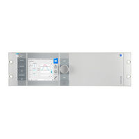
Maschinenfabrik Reinhausen TAPCON Operating Instructions Manual (318 pages)
Brand:
Maschinenfabrik Reinhausen
| Category:
Controller
| Size: 14 MB
Table of Contents
Table of Contents
3
1 Introduction
10
Manufacturer
10
Completeness
10
Safekeeping
10
Notation Conventions
10
Hazard Communication System
10
Information System
12
Instruction System
12
Typographic Conventions
13
2 Safety
14
Appropriate Use
14
Fundamental Safety Instructions
14
Personnel Qualification
17
Personal Protective Equipment
18
3 Security
19
4 Product Description
23
Scope of Delivery
23
Function Description of the Voltage Regulation
23
Performance Features
24
Operating Modes
25
Design
26
Operating Elements
27
Display Elements
28
Additional Operating Controls and Display Elements When Using the Mcontrol Touch Panel (Optional)
32
Front Interface
33
Assemblies
33
Operating Concept
38
5 Packaging, Transport and Storage
43
Suitability, Structure and Production
43
Markings
43
Transportation, Receipt and Handling of Shipments
43
Storage of Shipments
44
6 Mounting
45
Preparation
45
Electromagnetic Compatibility
45
Wiring Requirement of Installation Site
46
Wiring Requirement of Operating Site
46
Wiring Requirement in Control Cabinet
47
Information about Shielding the CAN Bus
48
Minimum Distances
49
Installing the 19-Inch Plug-In Housing
49
Installing the Individual Components on a Cap Rail
52
Fastening the Cap Rail
53
Installing the Bus Rail on the Cap Rail
53
Installing the Assembly at a Distance on the Cap Rail
54
Connecting the Device
55
Cable Recommendation
56
Information about Connecting Serial Interfaces RS232 and RS485
56
Information about Laying Fiber-Optic Cable
58
Mounting Terminating Resistor of CAN Bus
59
Connecting Cables to the System Periphery
59
Wiring the CPU Assembly
60
Wiring the UI Assembly
61
Wiring the AIO 2/AIO 4/AIO 8 Assembly
63
Wiring the DIO Assembly
67
Wiring the MC 2-2/SW3-3 Assembly
68
Connecting the Power Supply
70
Checking Functional Reliability
71
7 Commissioning
72
Performing Tests
72
Ground Test
72
Performing a Dielectric Test
74
Setting the Language
76
Setting Date and Time
77
Commissioning Wizard
77
Function Tests
78
Checking Measured Values and Status of Digital Inputs and Outputs
79
Testing a Control Function
79
Checking Parallel Operation
80
8 Operation
85
Establishing Connection to Visualization
85
Carrying out Tap-Change Operation Manually
87
General
87
Setting General Device Functions
87
Set up Automatic Logout
89
Activating/Deactivating Service User Access
89
Configuring the Network
90
Mqtt
93
Setting the Device Time
95
Time Synchronization Via PTP
96
Configuring Syslog
97
Setting the Screensaver
98
Scada
99
Configuring IEC 61850 (Optional)
99
Configuring IEC 60870-5-101 (Optional)
101
Configuring IEC 60870-5-103 (Optional)
104
Configuring IEC 60870-5-104 (Optional)
106
Configuring Modbus (Optional)
108
Configuring DNP3 (Optional)
110
Configuring GOOSE (Optional)
112
Configure Data Points (Optional)
117
Linking Signals and Events
124
Linking Functions
125
Linking Digital Outputs
127
Linking Control System Messages
128
Control of the Motor-Drive Unit
129
Setting the Switching Pulse for Controlling the Motor-Drive Unit
129
Setting Motor Runtime Monitoring
131
Setting the Switching Direction
131
Regulation
132
Response to Control System Disconnection (Optional)
132
Voltage Regulation
134
Setting the Desired Value
134
Transformer Data
150
Setting Transformer Data
151
Circuit Examples for Voltage Transformers and Current Transformers
152
Measurement
162
UI Measuring Channels
162
Control Variable
163
Regulation Mode
163
Display Power Factor Negative
163
Line Drop Compensation
164
R&X Compensation
164
Z Compensation
164
Tap Position Capture
167
Digital Tap Position Capture
168
Analog Tap Position Capture
168
Parallel Operation (Optional)
170
Parallel Operation Methods
170
Configuring Parallel Operation
175
TAPCON® 2Xx Retrofit
179
Detecting Parallel Operation Via Group Inputs (Optional)
180
Detecting Parallel Operation Via Topology
180
Setting Bank Parallel Operation
182
Monitoring Functions
182
Voltage Monitoring
183
Current Monitoring
185
Power Monitoring
188
Power Flow Monitoring
190
Tap Position Monitoring (Optional)
192
U Bandwidth Monitoring
194
Switching Interval Monitoring
196
Target-Tap-Position Operation
198
Measured Values
198
Displaying Current Measured Values
198
Displaying Measured Value Recorder (Optional)
199
Setting the Measured Value Recorder
204
Displaying Temperature Curve (Optional)
205
On-Load Tap-Changer Monitoring
206
Information about the On-Load Tap-Changer
206
Displaying Tap-Change Operation Statistics (Optional)
206
Displaying Information about Contact Wear (Only OILTAP®)
207
Maintenance (Optional)
208
Setting Operator Interval for OLTC Maintenance
209
Setting Operator Interval for Transformer Maintenance
210
Undertaking and Confirming Maintenance
211
Displaying Maintenance Overview
214
Configuring Analog Inputs and Outputs (Optional)
214
Configuring Digital Inputs and Outputs
217
Event Management
219
Displaying and Acknowledging Events
219
Configuring Events
220
Displaying Event Memory
221
User Administration
222
User Roles
223
Changing the Password
224
Creating, Editing and Deleting Users
225
Setting Access Rights to Parameters and Events
227
User Authentication Via RADIUS (Optional)
228
Information about Device
230
Hardware
230
Software
230
Parallel Operation
231
Topology
232
Import/Export Manager
233
Exporting Data
233
Importing Data (Software Version 3.44 and Later)
234
Configuring Media Converter with Managed Switch
235
Commissioning
235
Configuration
237
TAPCON® Personal Logic Editor (TPLE)
238
Function
238
Configuring TPLE
251
9 Maintenance and Care
255
10 Fault Elimination
256
General Faults
256
No Regulation in AUTO Mode
256
Bank Parallel Operation
257
Unwanted On-Load Tap-Change Operation
257
Human-Machine Interface
257
Incorrect Measured Values
258
Parallel Operation Faults
259
Tap Position Capture Incorrect
260
Assemblies
260
Other Faults
261
11 Event Messages
262
12 Uninstallation
271
Uninstalling the CPU Assembly
271
Uninstalling the UI 1/UI 3 Assembly
274
Uninstalling the AIO 2/AIO 4 Assembly
276
Uninstalling the DIO 28-15/DIO 42-20 Assembly
277
Uninstalling the MC 2-2/SW 3-3 Assembly
279
Uninstalling the QS3.241 Assembly
281
Uninstalling the Bus Rail
282
13 Disposal
283
14 Overview of Parameters
284
15 Technical Data
295
Display Elements
295
Voltage Supply
295
Voltage Measurement and Current Measurement
296
Digital Inputs and Outputs
297
Analog Inputs and Outputs
300
CPU (Central Processing Unit) I
301
System Networking
303
Dimensions and Weight
305
Ambient Conditions
306
Standards and Directives
307
Glossary
310
List of Key Words
312
Advertisement
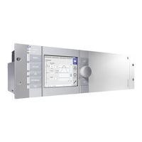
Maschinenfabrik Reinhausen TAPCON Operating Instructions Manual (306 pages)
Voltage Regulator
Brand:
Maschinenfabrik Reinhausen
| Category:
Controller
| Size: 15 MB
Table of Contents
Table of Contents
3
1 Introduction
9
Manufacturer
9
Completeness
9
Safekeeping
9
Notation Conventions
9
Hazard Communication System
9
Information System
11
Instruction System
11
Typographic Conventions
12
2 Safety
13
Appropriate Use
13
Fundamental Safety Instructions
13
Personnel Qualification
15
Personal Protective Equipment
16
3 IT Security
18
4 Product Description
22
Scope of Delivery
22
Function Description of the Voltage Regulation
22
Performance Features
23
Operating Modes
24
Design
26
Operating Controls
27
Display Elements
28
Additional Operating Controls and Display Elements When Using the Mcontrol Touch Panel (Optional)
32
Front Interface
33
Assemblies
33
Operating Concept
38
5 Packaging, Transport and Storage
42
Suitability, Structure and Production
42
Markings
42
Transportation, Receipt and Handling of Shipments
42
Storage of Shipments
43
6 Mounting
44
Preparation
44
Mounting Device
45
Connecting Device
48
Cable Recommendation
49
Information about Connecting Serial Interfaces RS232 and RS485
50
Information about Laying Fiber-Optic Cable
54
Electromagnetic Compatibility
54
Mounting Terminating Resistor of CAN Bus
60
Connecting Cables to the System Periphery
60
Wiring Device
60
Checking Functional Reliability
62
7 Commissioning
63
Setting Parameters
63
Commissioning Wizard
63
Setting the Parameters Manually
64
Function Tests
68
Checking Measured Values and Status of Digital Inputs and Outputs
68
Testing a Control Function
68
Checking Parallel Operation
69
8 Operation
75
General
75
Activating/Deactivating Automatic Launch of Commissioning Wizard
75
Setting Measured Value Display
76
Remote Behavior
76
Visualization
76
Activating/Deactivating the USB Interface
80
Control
80
Setting the Desired Value
81
Bandwidth
95
Delay Time T1
96
Delay Time T2
98
Transformer Data
101
Setting the Primary Transformer Voltage
101
Setting the Secondary Transformer Voltage
101
Setting Primary Transformer Current
102
Setting the Secondary Transformer Current
102
Setting Circuit for Current Transformer/Voltage Transformer and Phase Angle Correction
102
Measurement
112
Setting UI Measuring Channels
112
Control Variable
112
Regulation Mode
113
Setting the Display for the Power Factor
113
Control of the Motor-Drive Unit
114
Setting the Switching Pulse for Controlling the Motor-Drive Unit
114
Setting Motor Runtime Monitoring
116
Setting the Switching Direction
117
Setting Switching Direction Monitoring
117
Line Drop Compensation
118
R&X Compensation
119
Z Compensation
120
Tap Position Capture
122
Digital Tap Position Capture
122
Analog Tap Position Capture
122
Parallel Operation (Optional)
125
Parallel Operation Methods
125
Configuring Parallel Operation
133
TAPCON® 2Xx Retrofit
141
Detecting Parallel Operation Via Group Inputs (Optional)
141
Detecting Parallel Operation Via Topology
142
Monitoring Functions
146
Voltage Monitoring
146
Current Monitoring
149
Power Monitoring
152
Power Flow Monitoring
153
Tap Position Monitoring (Optional)
155
Bandwidth Monitoring
156
Phase Symmetry Monitoring
158
Switching Interval Monitoring
159
Target-Tap-Position Operation
161
Configuring Analog Inputs and Outputs (Optional)
161
Configuring Digital Inputs and Outputs
164
Displaying Temperature Curve (Optional)
166
Scada
166
Configuring IEC 61850 (Optional)
167
Displaying IEC 61850 Log (Optional)
169
Configuring IEC 60870-5-101 (Optional)
170
Configuring IEC 60870-5-103 (Optional)
174
Configuring IEC 60870-5-104 (Optional)
177
Configuring Modbus (Optional)
179
Configuring DNP3 (Optional)
182
Configuring GOOSE (Optional)
186
Configure Data Points (Optional)
191
Time Synchronization
199
Activating Time Synchronization Using SNTP
200
Entering the Time Server Address
201
Setting the Time Zone
201
Setting Synchronization Interval
202
Reference Time
202
User Administration
202
User Roles
203
Changing Password
204
Creating, Editing and Deleting Users
205
Setting Access Rights to Parameters and Events
207
Event Management
208
Displaying and Acknowledging Events
208
Configuring Events
208
Displaying Event Memory
210
Measured Values
211
Displaying Current Measured Values
212
Displaying Measured Value Recorder (Optional)
212
Setting the Average Value Interval
216
Information about Device
217
Hardware
217
Software
218
Parallel Operation
218
Topology
220
Information about the On-Load Tap-Changer
221
Import/Export Manager
221
Exporting Data
221
Importing Data (Software Version 3.44 and Later)
222
Configuring Media Converter with Managed Switch
223
Commissioning
223
Configuration
225
Linking Signals and Events
226
Linking Functions
227
Linking Digital Outputs and Control System Messages
229
Setting Screensaver
230
TAPCON® Personal Logic Editor (TPLE)
232
Function
232
Configuring TPLE
246
Maintenance (Optional)
249
Setting Operator Interval for OLTC Maintenance
250
Setting Operator Interval for Transformer Maintenance
252
Undertaking and Confirming Maintenance
252
Displaying Maintenance Overview
253
Displaying Tap-Change Operation Statistics (Optional)
254
Displaying Information about Contact Wear (Only OILTAP®)
255
9 Maintenance and Care
256
10 Fault Elimination
257
General Faults
257
No Regulation in AUTO Mode
257
Unwanted On-Load Tap-Change Operation
258
Human-Machine Interface
258
Incorrect Measured Values
259
Parallel Operation Faults
260
Tap Position Capture Incorrect
261
Assemblies
262
Other Faults
262
11 Messages
264
Event Messages
264
12 Disposal
273
13 Overview of Parameters
274
14 Technical Data
287
Display Elements
287
Voltage Supply
287
Voltage Measurement and Current Measurement
288
Digital Inputs and Outputs
289
Analog Inputs and Outputs
291
Central Processing Unit
292
System Networking
294
Dimensions and Weight
295
Ambient Conditions
296
Standards and Directives
297
Glossary
300
List of Key Words
301
Advertisement
Related Products
Maschinenfabrik Reinhausen TAPCON 230 expert
Maschinenfabrik Reinhausen TAPCON 250
Maschinenfabrik Reinhausen Categories
Controller
Industrial Equipment
Measuring Instruments
Test Equipment
More Maschinenfabrik Reinhausen Manuals
Login
Sign In
OR
Sign in with Facebook
Sign in with Google
Upload manual
Upload from disk
Upload from URL