Sign In
Upload
Manuals
Brands
Magtrol Manuals
Transducer
TM 308
Magtrol TM 308 Manuals
Manuals and User Guides for Magtrol TM 308. We have
2
Magtrol TM 308 manuals available for free PDF download: User Manual
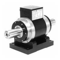
Magtrol TM 308 User Manual (48 pages)
In-Line Torque Transducers
Brand:
Magtrol
| Category:
Transducer
| Size: 2.94 MB
Table of Contents
Safety Precautions
3
Revisions to this Manual
4
Revision DATE
4
Table of Contents
5
Table of Contents
6
Table of FIGURES
6
Preface
7
Purpose of this MANUAL
7
Who Should USE this MANUAL
7
MANUAL Organization
7
Operating Principles
7
1 Introduction
9
Introduction
9
GENERAL Information
9
Description
9
Figure 1-1 TMB 313 In-Line Torque Transducer
9
DATA Sheets
10
Tm 301 - Tm 308
10
Introduction
12
Tm 309 - Tm 313
14
Tm 314 - Tm 317
20
Installation / Configuration
25
2 Installation / Configuration
25
Mounting Possibilities
25
Suspended Installation
25
Supported Installation
25
Figure 2-1 Suspended Installation
25
Tm/Tmb in Vertical Installation
26
PARASITIC Forces
26
Figure 2-2 Supported Installation
26
Figure 2-3 Parasitic Forces
26
Radial Forces (Bending)
27
Axial Forces (Thrust)
28
MEASURING Shaft Vibrations
29
Permitted Vibrations on Measuring Shaft
29
Figure 2-4 Radial Displacement
29
Figure 2-5 Vibratory Acceleration
30
Torque Signal Conditioning Electronic Circuit
31
Installation / Configuration
31
Figure 2-6 SW1 - SW12 Micro-Switches and Offset Adjustment Potentiometer
31
Mounting LIMITS
32
Dynamic Torque
32
Natural Frequency of Drive Train
32
Figure 2-7 Simplified Drive Train Model
32
Figure 2-8 Frequency Response Graph
33
Natural Measuring Shaft Torsional Frequency
34
Maximum Dynamic Amplitude
35
Protective Systems
35
Figure 2-9 Admissible Dynamic Load
35
Figure 2-10 Example of Protective System
36
Electronic SIGNAL Processing
37
Model 3410 Torque Display
37
Figure 2-11 Model 3410 Torque Display
37
Figure 2-12 PC-Based System Configuration with Model 3410 Display
37
Model 6400 Torque Transducer Display
38
Figure 2-13 Model 6400 Torque Transducer Display
38
Figure 2-14 PC-Based System Configuration with Model 6400 Display
38
Model DSP6001 Programmable Dynamometer Controller
39
Figure 2-15 Model DSP6001 Programmable Dynamometer Controller
39
Figure 2-16 PC-Based System Configuration with Model DSP6001 Controller
39
ELECTRICAL Connections
40
Grounding
40
Figure 2-17 Common Grounding
40
Connecting Cable
41
Figure 2-18 6-Pin Souriau Connector Configuration
41
Figure 2-19 14-Pin Centronics Connector Configuration
41
Connection to Non-Magtrol Electronics
42
Figure 2-20 Wiring Diagram for Connection to Non-Magtrol Electronics
42
Figure 2-21 er 107 Pin Configuration
43
Operating Principles
44
3 Operating Principles
44
Torque TRANSDUCER Architecture
44
Figure 3-1 TM Torque Transducer Principal Elements
44
Differential Transformer
45
SPEED Conditioning Chain
45
Built-IN SELF-TEST CIRCUIT
45
4 Maintenance / Repair
46
Maintenance / Repair
46
Maintenance
46
Repair
47
Service Information
48
RETURNING Magtrol Equipment for REPAIR And/Or Calibration
48
Returning Equipment to Magtrol, Inc. (United States)
48
Returning Equipment to Magtrol SA (Switzerland)
48
Advertisement
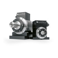
Magtrol TM 308 User Manual (44 pages)
IN-LINE TORQUE TRANSDUCERS
Brand:
Magtrol
| Category:
Transducer
| Size: 6.04 MB
Table of Contents
Table of Contents
5
Preface
7
1 Introduction
9
General Information
9
Tm Transducer Range Presentation
9
Datasheet
10
2 Installation / Configuration
21
Mounting Possibilities
21
Suspended Installation
21
Supported Installation
22
TM / TMB in Vertical Installation
22
Parasitic Forces
23
Radial Forces (Bending)
23
Axial Forces (Thrust)
24
Measuring Shaft Vibrations
25
Permitted Vibrations on Measuring Shaft
25
Torque Signal Conditioning Electronic Circuit
27
Mounting Limits
28
Dynamic Torque
28
Natural Frequency of Drive Train
28
Natural Measuring Shaft Torsional Frequency
30
Maximum Dynamic Amplitude
30
Protective Systems
31
Electronic Signal Processing
32
MODEL 3411 - Torque Display
32
DSP 7000 - High-Speed Programmable Dynamometer Controller
33
Electrical Connections
34
Grounding
34
Connecting Cable
35
Cable Assembly ER107 (Pigtail Wires)
35
Cable Assembly ER113 (14-Pin Connector)
35
Connection to Non-Magtrol Electronics
36
3 Operating Principles
39
Torque Transducer Architecture
39
Differential Transformer
39
Speed Conditioning Chain
40
Built-In Self-Test Circuit (B.I.t.e.)
40
4 Maintenance, Repair & Calibration
41
Maintenance
41
Repair
42
Calibration
42
Packaging
42
Services Information
42
Returning Equipment to Magtrol Inc. (United States)
43
Returning Equipment to Magtrol S.a. (Switzerland)
44
Advertisement
Related Products
Magtrol TM 300 Series
Magtrol TM 301
Magtrol TM 302
Magtrol TM 303
Magtrol TM 304
Magtrol TM 305
Magtrol TM 306
Magtrol TM 307
Magtrol TM 309
Magtrol TM 313
Magtrol Categories
Measuring Instruments
Controller
Power Supply
Monitor
Transducer
More Magtrol Manuals
Login
Sign In
OR
Sign in with Facebook
Sign in with Google
Upload manual
Upload from disk
Upload from URL