Sign In
Upload
Download
Table of Contents
Contents
Add to my manuals
Delete from my manuals
Share
URL of this page:
HTML Link:
Bookmark this page
Add
Manual will be automatically added to "My Manuals"
Print this page
×
Bookmark added
×
Added to my manuals
Manuals
Brands
Magtrol Manuals
Transducer
TM 300 Series
User manual
Magtrol TM 300 Series User Manual
In-line torque transducers
Hide thumbs
1
2
3
4
Table Of Contents
5
6
7
8
9
10
11
12
13
14
15
16
17
18
19
20
21
22
23
24
25
26
27
28
29
30
31
32
33
34
35
36
37
38
39
40
41
42
43
44
45
46
47
48
page
of
48
Go
/
48
Contents
Table of Contents
Bookmarks
Table of Contents
Safety Precautions
Revisions to this Manual
Revision DATE
Table of Contents
Table of Contents
Table of FIGURES
Preface
Purpose of this MANUAL
Who Should USE this MANUAL
MANUAL Organization
Operating Principles
1 Introduction
Introduction
GENERAL Information
Description
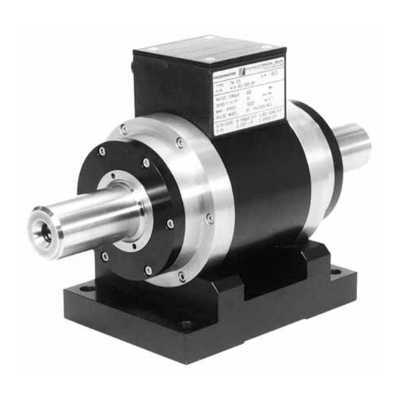
Figure 1-1 TMB 313 In-Line Torque Transducer
DATA Sheets
Tm 301 - Tm 308
Introduction
Tm 309 - Tm 313
Tm 314 - Tm 317
Installation / Configuration
2 Installation / Configuration
Mounting Possibilities
Suspended Installation
Supported Installation
Figure 2-1 Suspended Installation
Tm/Tmb in Vertical Installation
PARASITIC Forces
Figure 2-2 Supported Installation
Figure 2-3 Parasitic Forces
Radial Forces (Bending)
Axial Forces (Thrust)
MEASURING Shaft Vibrations
Permitted Vibrations on Measuring Shaft
Figure 2-4 Radial Displacement
Figure 2-5 Vibratory Acceleration
Torque Signal Conditioning Electronic Circuit
Installation / Configuration
Figure 2-6 SW1 - SW12 Micro-Switches and Offset Adjustment Potentiometer
Mounting LIMITS
Dynamic Torque
Natural Frequency of Drive Train
Figure 2-7 Simplified Drive Train Model
Figure 2-8 Frequency Response Graph
Natural Measuring Shaft Torsional Frequency
Maximum Dynamic Amplitude
Protective Systems
Figure 2-9 Admissible Dynamic Load
Figure 2-10 Example of Protective System
Electronic SIGNAL Processing
Model 3410 Torque Display
Figure 2-11 Model 3410 Torque Display
Figure 2-12 PC-Based System Configuration with Model 3410 Display
Model 6400 Torque Transducer Display
Figure 2-13 Model 6400 Torque Transducer Display
Figure 2-14 PC-Based System Configuration with Model 6400 Display
Model DSP6001 Programmable Dynamometer Controller
Figure 2-15 Model DSP6001 Programmable Dynamometer Controller
Figure 2-16 PC-Based System Configuration with Model DSP6001 Controller
ELECTRICAL Connections
Grounding
Figure 2-17 Common Grounding
Connecting Cable
Figure 2-18 6-Pin Souriau Connector Configuration
Figure 2-19 14-Pin Centronics Connector Configuration
Connection to Non-Magtrol Electronics
Figure 2-20 Wiring Diagram for Connection to Non-Magtrol Electronics
Figure 2-21 er 107 Pin Configuration
Operating Principles
3 Operating Principles
Torque TRANSDUCER Architecture
Figure 3-1 TM Torque Transducer Principal Elements
Differential Transformer
SPEED Conditioning Chain
Built-IN SELF-TEST CIRCUIT
4 Maintenance / Repair
Maintenance / Repair
Maintenance
Repair
Service Information
RETURNING Magtrol Equipment for REPAIR And/Or Calibration
Returning Equipment to Magtrol, Inc. (United States)
Returning Equipment to Magtrol SA (Switzerland)
Advertisement
Quick Links
1
General Information
2
Tm 301 - Tm 308
3
Data Sheets
4
Tm 309 - Tm 313
Download this manual
TM 300 Series
In-Line Torque Transducers
User's Manual
Via Paolo Uccello 4 - 20148 Milano
Tel +39 02 48 009 757 Fax +39 02 48 002 070
info@dspmindustria.it www.dspmindustria.it
Table of
Contents
Previous
Page
Next
Page
1
2
3
4
5
Advertisement
Table of Contents
Need help?
Do you have a question about the TM 300 Series and is the answer not in the manual?
Ask a question
Questions and answers
Related Manuals for Magtrol TM 300 Series
Transducer Magtrol TM Series User Manual
In-line torque transducers (44 pages)
Transducer Magtrol TMHS Series User Manual
In-line torque transducers (48 pages)
This manual is also suitable for:
Tmb series
Tm 301
Tmhs series
Tm 302
Tm 303
Tm 304
...
Show all
Tm 305
Tm 306
Tm 307
Tm 308
Tm 309
Tm 310
Tm 311
Tm 312
Tm 313
Tmb 302
Tmb 301
Tmb 303
Tmb 304
Tmb 307
Tmb 305
Tmb 306
Tmb 308
Tmb 309
Tmb 311
Tmb 310
Tmb 312
Tmb 313
Tmhs 301
Tmhs 302
Tmhs 303
Tmhs 304
Tmhs 306
Tmhs 305
Tmhs 308
Tmhs 307
Tmhs 309
Tmhs 310
Tmhs 312
Tmhs 311
Tm 314/x21
Tmhs 313
Tm 315/x21
Tm 316/x21
Tm 314/x31
Tm 315/x31
Tm 317/x21
Tmhs 314/x21
Tmhs 314/x31
Tmhs 315/x21
Tmhs 315/x31
Tmhs 316/x21
Tmhs 317/x21
Table of Contents
Print
Rename the bookmark
Delete bookmark?
Delete from my manuals?
Login
Sign In
OR
Sign in with Facebook
Sign in with Google
Upload manual
Upload from disk
Upload from URL


Need help?
Do you have a question about the TM 300 Series and is the answer not in the manual?
Questions and answers