Sign In
Upload
Manuals
Brands
Magnum Energy Manuals
Network Router
ME-ARTR
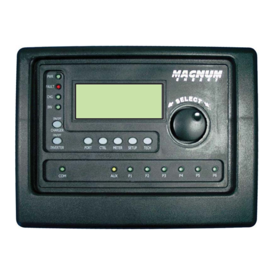
Magnum Energy ME-ARTR Advanced Router Manuals
Manuals and User Guides for Magnum Energy ME-ARTR Advanced Router. We have
1
Magnum Energy ME-ARTR Advanced Router manual available for free PDF download: Owner's Manual
Magnum Energy ME-ARTR Owner's Manual (182 pages)
Advanced Router
Brand:
Magnum Energy
| Category:
Network Router
| Size: 1 MB
Table of Contents
Contact Information
2
Copyright Notice
2
Safety Information
3
Safety Symbols
3
Table of Contents
4
1 Introduction
10
Figure 1-1, Front Panel Features
10
Figure 1-2, Router Features (Front Cover Removed)
11
2 Installation
12
Pre-Installation
12
Inverter Requirements
12
Installation Guidelines
12
Unpacking and Inspection
12
Tools Required
12
Installation Overview
13
Figure 2-1, System Overview
13
Router Dimensions
14
Figure 2-2, Router Dimensions (with Front Cover)
14
Figure 2-3, Router Mounting Holes and Cutout Sections (Back)
14
Communications Cables - Provided
15
Network Cable
15
Figure 2-4, Remote (RJ14) Communication Cable
15
Figure 2-5, Parallel Stack (RJ45) Communication Cable
15
Communications Cable Routing
16
Figure 2-6, Concealed Mounted Remote/Network Cables
16
Figure 2-7, Surface Mounted Remote/Network Cables
16
Figure 2-8, Router Front Cover's Cable Connection Cutouts
16
Mounting the Router on a Wall
17
Connecting the Communication Cables
17
Figure 2-9, Mounting the Router to a Wall
17
Connecting the Remote/Network Cables
18
Figure 2-10, Connecting the Parallel Stack and Remote Cables to an Inverter
18
Connecting the Parallel Stack Cables
19
Installing the Router's
19
Figure 2-11, Connecting the Parallel Stack Cables to the Router
19
Figure 2-12, Installing the Router's Front Cover
19
Wiring the Auxiliary (Aux) Relay
20
Figure 2-13, Wiring the Auxiliary Relay
20
3 Setup
21
Power-Up Routine
21
Navigating the Router
21
Figure 3-1, System Home Screen
21
Figure 3-2, up and down Arrows for Hidden Lines
21
Router Buttons and Menu Items
22
PORT Button and Menus
22
Figure 3-3, PORT Button
22
CTRL (Control) Button and Menus
23
Figure 3-4, CTRL (Control) Button and Menus
23
METER Button and Menus
27
Figure 3-5, METER Button and Menus
27
Figure 3-6, Current Flow - Inverter Mode
30
Figure 3-7, Current Flow - Standby Mode
30
Figure 3-8, Current Flow - Load Support Mode
30
Figure 3-9, ALL Ports Vs Port-Specific METER Menus
31
Figure 3-10, Accessing Port-Specific METER Menus
31
SETUP Button and Menus
32
Figure 3-11, SETUP Button
32
Table 3-1, Battery Type to Charge Voltages
42
Figure 3-12, CV Charge Done Time/Amps Charge Stages
44
Figure 3-13, Hold CV Charge Volts CC/CV Charge Stages
45
Table 3-2, Battery Amp/Hrs Capacity to Suggested Absorb Time
46
Figure 3-14, Final Charge Stage - Multi-Stage
50
Figure 3-15, Final Charge Stage - Float
50
Figure 3-16, Final Charge Stage - Silent
50
TECH Button and Menus
52
Figure 3-17, TECH Button
52
Figure 3-18, Port-Specific TECH Menus
53
Figure 3-19, Inverter Fault History (First and Second Screens)
54
Figure 3-20, AGS Fault History
54
Figure 3-21, PT Controller Fault History (First and Second Screens)
54
Table 3-3, Inverter/Charger Default Settings on ME-ARTR
56
4 ME-ARTR Menu Maps
57
Figure 4-1, PORT/CTRL Button Menu Maps
57
Figure 4-2, METER Button (ALL Ports & Port-Specific) Menu Map
58
Figure 4-3, SETUP Button (System and Inverter Setup - ALL Ports) Menu Map
59
Figure 4-4, SETUP Button (Charger Setup - ALL Ports) Menu Map
60
Figure 4-5, TECH Button (ALL Ports) Menu Map
61
Figure 4-6, TECH Button (Single Ports) Menu Map
62
Figure 4-7, Legend Key for Menu Maps
62
5 Operation
63
Front Panel
63
LED Indicators
63
LCD Display
63
Figure 5-1, ME-ARTR Front Panel Controls and Indicators
63
ON/OFF Buttons
64
Menu Buttons
64
Rotary SELECT Knob
64
Aux Relay LED Indicator
64
Figure 5-2, Aux Relay LED
64
Operating the Inverter/Charger
65
Inverter Mode
65
Charger Mode
65
System Status Messages
65
Inverter Mode Status Messages
66
Figure 5-3, SYSTEM Status Home Screens
66
Figure 5-4, Empty
66
Figure 5-5, Inverting Mode
66
Charger Mode Status Messages
67
Figure 5-6, Inverter Standby Mode
67
Figure 5-7, off Mode
67
Figure 5-8, Searching Mode
67
Figure 5-9, Unknown Mode
67
Figure 5-10, Absorb Charging Mode
68
Figure 5-11, Bulk Charging Mode
68
Figure 5-12, Charger Standby Mode
68
Figure 5-13, Charging Mode
68
Figure 5-14, Constant Current Mode
69
Figure 5-15, Constant Voltage Mode
69
Figure 5-16, Equalizing Mode
69
Figure 5-17, Float Charging Mode
70
Figure 5-18, Full Charge Mode
70
Figure 5-19, Load Support AAC Mode
71
Figure 5-20, Load Support VDC Mode
71
Figure 5-21, Silent Mode
71
Secondary Scrolling Status Messages
72
Figure 5-22, AC in - Disabled Mode
72
Figure 5-23, Gen Cooldown Mode
72
Figure 5-24, Gen Warm-Up Mode
72
Figure 5-25, Inv Max Charge Time Mode
73
Figure 5-26, PT Max Charge Time
73
Figure 5-27, Reminder to EQ Mode
74
Figure 5-28, SOC Connect Mode
74
Figure 5-29, Time Connect Mode
74
Figure 5-30, VDC Connect Mode
74
Fault Mode Messages
75
Figure 5-31, AC Backfeed Mode
75
Figure 5-32, AC Overload Fault
75
Figure 5-33, Breaker Tripped Fault
76
Figure 5-34, Dead Battery Charge Fault
76
Figure 5-35, FET Overload Fault
76
Figure 5-36, High Battery Fault
77
Figure 5-37, High Battery Temperature
77
Figure 5-38, High Speed Bus Fault
77
Figure 5-39, High Volts AC Fault
78
Figure 5-40, Low Battery Fault
78
Figure 5-41, no Inverter Found
78
Figure 5-42, Overcurrent Fault
79
Figure 5-43, Overtemp Fault
79
Figure 5-44, Stuck Relay Fault
79
Figure 5-45, Tfmr Overtemp Fault
80
Figure 5-46, Unknown Fault
80
Figure 5-47, Stackclock Fault
81
Figure 5-48, Stack Mode Fault
81
Figure 5-49, Stackphase Fault
81
Figure 5-50, Internal Bridge Fault
82
Figure 5-51, Internal Charger Fault
82
Figure 5-52, Internal NTC Fault
82
Figure 5-53, Internal Relay Fault
82
LED Indicator Guide
83
Table 5-1, LED Indicator Guide
83
6 Troubleshooting
84
Table 6-1, Router Troubleshooting Guide
84
Troubleshooting Tips
85
Inverter Problems
85
Charger Problems
85
Performing an Inverter Reset
86
Powering down the Inverter
86
Figure 6-1, Performing an Inverter Reset
86
7 Updating the ME-ARTR Router's Firmware
87
Figure 7-1, ME-ARTR Router's Firmware SD Card Slot
87
8 Using an AGS Module
88
Software Differences between AGS Versions
88
Figure 8-1, ME-Artr's AGS Configuration Access Buttons
88
Table 8-1, Software Differences between AGS Versions
89
ME-AGS-N Setup (with the ME-ARTR)
90
Table 8-2, ME-ARTR Autostart/Autostop Matrix
90
ME-AGS-N Functional Tests Using the ME-ARTR
102
ME-AGS-N Operation/Monitoring (with the ME-ARTR)
103
Controlling the AGS Using the ME-ARTR
103
Enabling the ME-AGS-N
104
Monitoring the AGS Using the ME-ARTR
104
Starting and Stopping the Generator
107
ME-ARTR Router's AGS Menu Maps
108
Figure 8-2, AGS PORT, CONTROL, METER, and TECH Menu Maps
108
Figure 8-3, AGS SETUP Menu Maps (Section 1)
109
Figure 8-4, AGS SETUP Menu Maps (Section 2)
110
ME-AGS-N Router Status Messages
111
Table 8-3, AGS Router Operational Statuses
111
Table 8-4, AGS Router Start Statuses
112
Table 8-5, AGS Router Fault Statuses
112
Table 8-6, AGS Default Settings on ME-ARTR
113
ME-AGS-N Router Troubleshooting (with the ME-ARTR)
114
AGS Fault Message Screens for the Router
114
Figure 8-5, ME-AGS-N Fault Message - Router Screens
114
Resolving AGS Faults Using Your Router
115
9 Using a BMK
117
ME-BMK Setup (with the ME-ARTR)
117
Adjusting the Charge Effi Ciency Setting
117
ME-BMK Operation/Monitoring (with the ME-ARTR)
118
How Does the ME-BMK Battery Monitor Operate
118
BMK METER Menu Items (with ME-ARTR)
119
Figure 9-1, Ending Battery Voltage Versus Time
119
ME-ARTR Router's BMK Menu Maps
121
Figure 9-2, BMK SETUP Menu Maps
121
Figure 9-3, BMK METER Menu Maps (ALL Ports)
122
Figure 9-4, BMK METER Menu Map (Port-Specific)
122
BMK Status Messages (with the ME-ARTR)
123
Table 9-1, BMK Router Operational Statuses
123
Table 9-2, BMK Router Fault Statuses
123
ME-BMK Troubleshooting (with the ME-ARTR)
124
BMK Fault Message Screens for a Magnum Router
124
Resolving BMK Faults Using the Router
124
Figure 9-5, ME-BMK Fault Message - Router Screens
124
10 Attaching a Remote Control
125
Figure 10-1, Accessing the RC Setup Menu
125
11 Using an ACLD
126
11.1 Setting up the ACLD Using the ME-ARTR
126
11.2 Monitoring the ACLD Using the ME-ARTR
126
11.2.1 ME-Artr's ACLD METER Button Menus
126
11.2.2 ME-ARTR Router's ACLD-Specifi C TECH Menus
127
11.2.3 ACLD Menu Maps
127
Figure 11-1, ACLD METER Menu Map
127
11.2.4 ACLD Router Status Messages
128
Table 11-1, ACLD Router Operational Statuses
128
11.3 ACLD Troubleshooting Using the ME-ARTR
129
11.3.1 ACLD Fault Message Screens
129
11.3.2 Resolving ACLD Faults Using the ME-ARTR
129
Figure 11-2, ACLD Fault Message (Example)
129
12 Using a PT Charge Controller
130
12.1 Setting up the PT Controller Using the ME-ARTR
130
Figure 12-1, CV Charge Done Time/Amps (PT Controller)
132
Figure 12-2, Hold CV Charge Volts (PT Controller)
133
Figure 12-3, Multi-Stage Charging (PT Controller)
134
12.2 Operating/Monitoring the PT Controller Using the ME-ARTR
139
12.2.1 Operating the PT Charge Controller
139
12.2.2 Monitoring the PT Charge Controller
142
12.2.3 PT Charge Controller Menu Maps
146
Figure 12-4, PT Charge Controller CTRL Menu Map
146
Table 12-1, PT Default Settings on ME-ARTR
146
Figure 12-5, PT Charge Controller METER Menu Map
147
Figure 12-6, PT Charge Controller Data History Matrix Menu Map
148
Figure 12-7, PT Charge Controller SETUP1 Menu Map
149
Figure 12-8, PT Charge Controller SETUP2 Menu Map
150
12.2.4 PT Charge Controller Router Status Messages
151
Table 12-2, PT Controller Router Operational Statuses
151
Table 12-3, PT Router Relay Statuses
151
Table 12-4, PT Router Fault Statuses
152
Table 12-5, PT Router Charge Modes
153
Table 12-6, PT Router Power Statuses
154
12.3 PT Controller Troubleshooting Using the ME-ARTR
155
12.3.1 PT Controller Fault Message Screens
155
12.3.2 Resolving PT Faults Using the ME-ARTR
155
Figure 12-9, PT Controller Fault Message (Example)
155
Appendix A - Router Display Abbreviations
160
Table A-1, Abbreviations on Router Display
160
Appendix B - Router Feature to Inverter Compatibility
165
Table B-1, ME-ARTR (Version 4.0) Compatibility Matrix
165
Appendix C - Using the Router with Non-Stacked Inverters
172
Using Router to Control Multiple Unconnected Inverters
172
Appendix D - Using the ME-ARTR in an AC Coupled Application
173
What Is an AC Coupled System
173
Confi Gure the Router to Use in an AC Coupled System
173
Appendix E - Warranty and Service Info
174
Limited Warranty
174
How to Receive Repair Service
174
Index
175
Advertisement
Advertisement
Related Products
Magnum Energy ME-ARC50
Magnum Energy ME-AGS-S
Magnum Energy ME-AGS-N
Magnum Energy ME-ARC Series
Magnum Energy ME-ARC
Magnum Energy ME-RTR
Magnum Energy ME2012-15B
Magnum Energy ME1512
Magnum Energy ME2012
Magnum Energy ME-MR
Magnum Energy Categories
Inverter
Remote Control
Battery Charger
Adapter
Measuring Instruments
More Magnum Energy Manuals
Login
Sign In
OR
Sign in with Facebook
Sign in with Google
Upload manual
Upload from disk
Upload from URL