Table of Contents
Advertisement
Advertisement
Table of Contents
Troubleshooting

Summary of Contents for Magnum Energy ME-ARTR
- Page 1 ME-ARTR Advanced Router Owner’s Manual (Version 4.0)
-
Page 2: Copyright Notice
If the ME-ARTR fails, it is reasonable to assume the health of the user or other persons may be endangered. -
Page 3: Safety Information
Safety Information Important Product Safety Instructions This manual contains safety instructions that must be followed during the installation and operation of this product. Read all instructions and safety information contained in this manual before installing or using this product. Safety Symbols To reduce the risk of electrical shock, fi... -
Page 4: Table Of Contents
CTRL (Control) Button and Menus ..............14 3.3.3 METER Button and Menus ................18 3.3.4 SETUP Button and Menus ................23 3.3.5 TECH Button and Menus ................43 ME-ARTR Menu Maps ................48 Operation ..................... 54 Front Panel ....................54 5.1.1 LED Indicators ....................54 5.1.2 LCD Display ....................54 5.1.3... - Page 5 ACLD Fault Message Screens ..............120 11.3.2 Resolving ACLD Faults using the ME-ARTR ............ 120 12.0 Using a PT Charge Controller .............. 121 12.1 Setting Up the PT Controller using the ME-ARTR ..........121 Page iv © 2017 Sensata Technologies...
- Page 6 Appendix C – Using the Router with Non-stacked Inverters ......163 Using Router to Control Multiple Unconnected Inverters ........163 Appendix D – Using the ME-ARTR in an AC Coupled Application ....164 What is an AC Coupled System ..............164 Confi...
- Page 7 Figure 4-5, TECH Button (ALL Ports) Menu Map ..............52 Figure 4-6, TECH Button (Single Ports) Menu Map .............53 Figure 4-7, Legend Key for Menu Maps ................53 Figure 5-1, ME-ARTR Front Panel Controls and Indicators ...........54 Figure 5-2, Aux Relay LED .....................55 Figure 5-3, SYSTEM Status Home Screens ...............57 Figure 5-4, Empty ......................57...
- Page 8 Figure 5-53, Internal Relay Fault ..................73 Figure 6-1, Performing an Inverter Reset .................77 Figure 7-1, ME-ARTR Router’s Firmware SD Card Slot ............78 Figure 8-1, ME-ARTR’s AGS Configuration Access Buttons ...........79 Figure 8-2, AGS PORT, CONTROL, METER, and TECH Menu Maps .........99 Figure 8-3, AGS SETUP Menu Maps (Section 1) ...............
- Page 9 Table 8-4, AGS Router Start Statuses ................103 Table 8-5, AGS Router Fault Statuses ................103 Table 8-6, AGS Default Settings on ME-ARTR ..............104 Table 9-1, BMK Router Operational Statuses ..............114 Table 9-2, BMK Router Fault Statuses ................114 Table 11-1, ACLD Router Operational Statuses ..............
-
Page 10: Introduction
MS-PE inverter/chargers in parallel, two AGS modules, six BMKs, and one remote control. Info: This manual is for the ME-ARTR with version 4.0 or higher; see the TECH: 02 Port Vers section on page 44 for information on how to determine your version level. -
Page 11: Figure 1-2, Router Features (Front Cover Removed)
SETUP button. • Auxiliary (Aux) Relay – The ME-ARTR provides an Auxiliary Relay (Item G below) that can be programmed to work either as a voltage-controlled relay (stays opened or closed based on VDC, and activates either as an active high or active low type relay with an adjustable time delay), a SOC-controlled relay (stays opened or closed based on the battery’s state of... -
Page 12: Installation
Pre-Installation Before proceeding, read the entire Installation section to determine how you are going to install your ME-ARTR router. Save time and avoid common, costly mistakes by thoroughly planning the installation before you start. 2.1.1 Inverter Requirements The router is used to control multiple Magnum inverters that are normally connected in parallel. -
Page 13: Installation Overview
Installation Installation Overview The simplifi ed system diagram shown in Figure 2-1 should be reviewed to assist you with planning and designing your installation. This drawing is not intended to override or restrict any national or local electrical codes, nor should it be the determining factor as to whether the installation is compliant—that is the responsibility of the electrician and the onsite inspector. -
Page 14: Router Dimensions
Installation Router Dimensions RIGHT FRONT " SIDE VIEW (16.8 cm) 9/16" " (22.7 cm) (4 cm) 15/16 " 9/16 (4 cm) BOTTOM " VIEW (1.6 cm) " (17.9 cm) " " 1/16 15/16 15/16 (2.4 cm) (2.4 cm) Figure 2-2, Router Dimensions (with Front Cover) 3/8"... -
Page 15: Communications Cables - Provided
Most systems that use the router will also use an enclosure that includes the components required in a parallel inverter system (i.e., Magnum Energy panels). The NEC/CEC requires the insulation of all conductors inside the enclosure to be rated for the highest voltage present. The router is designed to work with 120/240 VAC inverters, therefore, the voltage rating of the communications cables inside the enclosure must be rated for 300 volts or higher to be code compliant. -
Page 16: Communications Cable Routing
(Figure 2-6); or, if there is insuffi cient room behind the wall or no desire to cut into the wall, the cables can be surface-mounted (Figure 2-7). Info: If the router is being installed on a Magnum Energy panel enclosure (MP), a router mounting bracket is provided with the panels. This bracket can be attached to either the left or right-hand side. -
Page 17: Mounting The Router On A Wall
Installation Mounting the Router on a Wall CAUTION: The router must be located close to the inverter/chargers (within six feet). The router is designed to exchange data from the master inverter with one or multiple slave inverters. The high speed communication data between the stack ports on the router and the inverter ensure the slave inverters are synchronized to the master inverter. -
Page 18: Connecting The Remote/Network Cables
Installation Once the stack cables are connected, coordinate the remote cables to the communications ports so that the Master inverter is connected to Port 1 and the Slave 1 inverter is connected to Port 2 (the remote and stack cables are connected to the inverters in order from left to right—MA (Master), SL1, SL2, and SL3). -
Page 19: Connecting The Parallel Stack Cables
Installation 2.7.2 Connecting the Parallel Stack Cables To connect the parallel stack cables: 1. Connect a stack cable to the Stack/Accessories port on every inverter installed in parallel (see Figures 2-1 & 2-10). 2. Route the inverter-connected stack cables from each inverter/charger to your router. Depending on your particular setup, the cables may need to be routed through walls or the MP panel enclosure system. -
Page 20: Wiring The Auxiliary (Aux) Relay
Installation Wiring the Auxiliary (Aux) Relay The router’s Aux Relay provides a 2-wire dry contact relay (i.e., no voltage provided) that is either open or closed, and can be wired to any device requiring a contact closure to operate. For example, it can be used as a signal relay to power a higher current relay. -
Page 21: Setup
When the router is fi rst connected to an inverter, a power-up routine is initialized. The LCD displays “MAGNUM ENERGY, Self Test, ME-ARTR, Version 4.0” for approximately 5 seconds. The next several Set System Clock screens prompt you to set the current time (HOURS, MINUTES, and AM/PM) and date (MM/DD/YYYY). -
Page 22: Router Buttons And Menu Items
Setup Router Buttons and Menu Items The fi ve menu buttons (PORT, CTRL, METER, SETUP, and TECH) allow the inverter/charger system to be confi gured to your specifi c preferences. These buttons also allow you to access menu items that can help with monitoring and troubleshooting your system. 3.3.1 PORT Button and Menus The PORT button allows you to access each active communication port. -
Page 23: Ctrl (Control) Button And Menus
Setup 3.3.2 CTRL (Control) Button and Menus The CTRL button accesses the 01 AC In Control, 02 Charger Control, 03 Gen Control, and 04 ARTR Aux Relay menus. Info: An AGS must be connected in order for the Gen Control menu to display unless the TECH: 08 Show all Menus menu has been set to “YES”. - Page 24 Setup CTRL: 01 AC In Control The 01 AC In Control menu has four different conditions in which the inverter/charger connects to an incoming AC power source. Only one may be selected—multiple conditions can be set up and enabled, but only one can be active at a time. Info: The top status line of the alternates the inverter/charger status with a secondary AC IN status when AC is present, but is not connecting as a result of a setting made in the SETUP menu.
- Page 25 Setup CTRL: 02 Charger Control The 02 Charger Control menu enables you to set the charge mode to Multi-Stage, Start Float, or to Start Bulk. Most of the time the charger should be left in the Multi-Stage setting, but to override this setting use the CTRL button and the 02 Charger Control menu.
- Page 26 Setup • Force Open – Manually forces the router’s Aux Relay contacts to stay open. This setting manually controls the device connected to the relay, or can be used to test relay operation. • Force Closed – Manually forces the router’s Aux Relay contacts to stay closed. This setting manually controls the device connected to the relay, or can be used to test relay operation.
-
Page 27: Meter Button And Menus
Setup 3.3.3 METER Button and Menus The METER button gives you access to the various meters which help determine the status of the inverter/charger and battery system. Info: Depending on the inverter, some meter functions may not be accessible. Refer to Appendix B for more information. - Page 28 Setup MS-PAE (menus 02C-02G) or MSH models only (menus 02C-02I): • 02C System AC Amps: AC Load: This meter is the sum of the values from the 02E AC Load Amps menu for each inverter connected in parallel (i.e., MS-PAE or PE Series). See the 02E AC Load Amps section for more information on how the AC load amps value is determined.
- Page 29 Setup MSH models only: • 02H Input Volts AC1: This menu displays the RMS value of the AC voltage at the inverter’s AC1 and NEUTRAL input terminals. MSH-RE models only: • 02I Input Volts AC2: This menu displays the RMS value of the AC voltage at the inverter’s AC2 and NEUTRAL input terminals.
-
Page 30: Figure 3-6, Current Flow - Inverter Mode
Setup INVERT MODE AC Input = Current from the battery is used by the inverter 0 Amps AC to power the inverter’s AC loads. DC CURRENT AC CURRENT MAGNUM Example below: (BATTERY) (GRID/GEN) INVERTER Current to inverter input (AC Input) = 0 Amps AC -120ADC 0AAC... -
Page 31: Figure 3-9, All Ports Vs Port-Specific Meter Menus
Setup 3.3.3.1 Additional METER Menus for Port-connected Inverters The METER button also provides meter displays for each active port-connected inverter (or accessory) in your system. These displays are similar to those in Section 3.3.3, but the displayed information is specifi c to the particular inverter and/or model (Figures 3-9 & 3-10 below). All Ports Inverter Single Port Note that menu... -
Page 32: Setup Button And Menus
Setup 3.3.4 SETUP Button and Menus Pressing the SETUP button provides access to the menu items and settings that enable you to confi gure the router display, the inverter/charger, a ME-AGS-N, and a ME-BMK. Review each menu item to determine if you need to adjust any settings to meet your system requirements. Info: The fi... - Page 33 Setup Info: If DC power is lost to the router, the 01B Screen Setup setting defaults back to the default settings (Contrast = 50%, Brightness = 50%). • 01C Power Save: This setting turns off the Power Save™ feature, or you can select a duration of time (from 1 to 60 minutes) that determines when the display goes into Power Save mode.
- Page 34 Setup Example – Active Low: Set Close Volts below Open Volts voltage. If the Close Volts voltage is set at 24.0 VDC and the Open Volts voltage is set at 29.0 VDC, the relay closes when the battery voltage drops to 24.0 VDC and opens when the battery voltage rises to 29.0 VDC. Use this configuration to control a battery exhaust fan, or as a simple PV charge controller.
- Page 35 Setup • 01I Days to remind when to EQ: This menu sets the number of days that must pass before the router will remind you to equalize your batteries. Note: Depending on type of battery selected, EQing may not be allowed. If this is the case, “EQ not allowed in this battery type”...
- Page 36 Setup Where should I set the LBCO setting? If your goal is to not discharge your batteries more than 20%*, then set the LBCO from 11.5 to 12.2 VDC (12-volt models), 23.0 to 24.4 VDC (24- volt models), or 46.0 to 48.8 (48-volt models). In some applications, such as those installed in an off-grid home or when doing a lot of RV dry-camping, you may want to cycle down to 50%* by setting the LBCO from 10.0-11.4 VDC (12-volt models), 20.0-22.8 VDC (24-volt models) or 40.0-45.6 VDC (48-volt models).
- Page 37 Setup • 02D AC In – Volts DC: Based on the inverter’s battery voltage, the AC In – Volts DC settings determine when the inverter automatically connects and disconnects the incoming utility power. ◊ Connect – This setting determines at what DC voltage the inverter/charger connects to incoming AC and transfers the loads from the inverter battery power to the utility grid.
- Page 38 Setup Info: The transfer to/from incoming AC occurs immediately when the Connect SOC or Disconnect SOC setting is reached. Info: A ME-BMK is required in order to use the 2E AC In – SOC setting. If this setting is selected and there is no ME-BMK installed in the system, or if a valid SOC number is not displayed under the METER/05 BMK Meters/05A SOC menu (i.e., Think’n, No Comm, Pwr-up Fault and Factory Fault are not valid SOC numbers), then the inverter will not connect to the incoming AC power.
- Page 39 Setup • 02G Inverter Threshold to Start Parallel (or, the “parallel threshold”): This setting is used for inverters in a parallel-stacked inverter system, and determines when the slave inverters turn on as a result of the percentage of power being provided by the master inverter Default setting: 60% Range: OFF, 30%-90% (10% increments) Info: Ensure the parallel threshold setting is not too high or the master inverter may...
- Page 40 Setup SETUP: 03 Charger Setup • 03A AC Input Amps: This setting ensures that the combined current draw from the battery charger and the AC loads does not exceed the maximum input current that is available from the incoming AC power. This setting is used to set that maximum input current level. Whenever the incoming AC is connected and passing thru the inverter, the current from the incoming AC used to power the AC loads and charge the batteries is monitored.
- Page 41 Setup Info: If you are supplying two AC sources (utility and generator) to the inverter’s single input through an AC transfer switch, adjust the AC Input Amps setting to the smaller AC circuit breaker side of the two AC sources. Info: The AC Input Amps setting is dependent on the stability of the AC source.
-
Page 42: Table 3-1, Battery Type To Charge Voltages
Setup • 03C Battery Type: This setting selects the battery type, which determines the battery charge profi le and ensures the batteries are receiving the proper charge voltage. The charge voltage settings are fi xed when using the GEL, Flooded, AGM1, or AGM2 selections, but can be adjusted if using the CC/CV or Custom selections. - Page 43 Setup ◊ Set Battery Type ( CC/CV) – The CC/CV selection provides a 2-stage (Constant Current/ Constant Voltage) charging cycle with an adjustable charge voltage and output current. Note: CC/CV settings only display if CC/CV has been selected from the 03 Battery Type menu. Info: If CV/CC has been selected from the 03C Battery Type menu, the following menus are no longer accessible and display “CC/CV Controlled”...
-
Page 44: Figure 3-12, Cv Charge Done Time/Amps Charge Stages
Setup Set CV Charge Done Amps – This setting determines how long the charger holds the battery voltage at the CV Chg Volts setting—based on a minimum current setting (i.e. done amps). During the Constant Voltage charge mode, as the battery charges, the current from the charger slowly decreases. -
Page 45: Figure 3-13, Hold Cv Charge Volts Cc/Cv Charge Stages
Setup □ Hold CV Chg Volts – This setting holds the battery voltage at the CV Chg Volts setting. This is for a system that requires a constant charge voltage to be present at all times. Constant Constant Voltage Current Max Charge CV Charge Amps... -
Page 46: Table 3-2, Battery Amp/Hrs Capacity To Suggested Absorb Time
Setup □ EQ Volts – Sets the level at which the charging voltage is held constant during an Equalization cycle. Note: Cannot be set lower than the Absorb Volts setting, or more than 2 volts (12v systems), 4 volts (24v), or 8 volts (48v) above the Absorb Volts setting. Default: 15.6 Volts (12v), 31.2 Volts (24v), 62.4 Volts (48v) Range: 12.0-16.0 Volts (12v), 24.0-32.0 Volts, 48.0-64.0 Volts (48v) □... - Page 47 Setup ◊ Set Absorb Done Amps – This setting is used when the DC amperage supplied to the batteries determines when the batteries are fully charged. During Absorb Charge mode—as the battery charges—the current required by the battery decreases. “Done amps” refers to when the done amps decreases below the Absorb Done Amps setting continuously for two minutes, the charger transfers from the Absorption charge cycle to the fi...
- Page 48 Setup • 03E Max Charge: This menu sets the maximum charge rate allowed to charge the batteries during Bulk, Absorption, Float, and Equalize charging, as well as sets a maximum time the charger is allowed to operate in either the Bulk or Absorption Charge mode. Note: If “CC/CV Controlled”...
- Page 49 Setup Where should I set my Max Charge Time? In order to ensure a complete charge cycle is accomplished, adjust the Max Charge: Time setting to a time period that is normally longer than the settings in the following SETUP menus: 03D Absorb Done Time, Absorb Done Amps, and Absorb Done SOC.
-
Page 50: Figure 3-14, Final Charge Stage - Multi-Stage
Setup Final Charge Stage: Multi-Stage Final Stage First Stage Second Stage Full Float Bulk Charging Absorb Charging Charge Charging Max Charge Float Absorb Amps Volts Volts Absorb Done (= Time, Amps or SOC) ReFloat Volts (restarts Float Charging for 4 hours, then back to Full Charge) Current... - Page 51 Setup ◊ Set Final Charge Stage = Silent – If Silent mode is selected as the fi nal charge stage, the charger stops charging once it transitions to ‘Silent’. Normally, the charger enters Silent mode after the absorption charge mode has fi nished, and after entering the Silent mode, the battery voltage is continuously monitored.
-
Page 52: Tech Button And Menus
Setup SETUP: 05 BMK Setup The ME-BMK/ME-BMK-NS (Battery Monitor Kit) accurately measures the SOC (State Of Charge), battery voltage, and the DC amps of the battery bank. Refer to Section 9.0 “Using a BMK” for detailed information on the available BMK menus using the router. Info: For installation information on the ME-BMK/ME-BMK-NS, refer to your BMK owner’s manual (PN: 64-0013) SETUP: 06 RC Setup... -
Page 53: Figure 3-18, Port-Specific Tech Menus
Setup • 01D AGS Sensor Temp – Displays the temperature of the AGS’s Battery Temp Sensor (BTS) that is connected to the battery bank. • 01E ACLD Temperature – Displays the internal temperature of the ACLD. • 01F PT Temps – Displays the temperature of each PT Controller’s Battery Temp Sensor (BTS), main power transformer, and Field Effect Transistors. -
Page 54: Figure 3-19, Inverter Fault History (First And Second Screens)
Setup Fault History Number Fault Mode Fault History Number Fault Mode Battery Temp Low Battery Low Battery Transformer Status 77F Tfmr 114F Temp 21.0VDC 12.0ADC FETs 102F DC Battery Amps 07/22/17 11:52A 07/22/17 11:52A Voltage Temp Time Port Date Time Port Date fault occurred... - Page 55 Setup TECH: 06 SETUP PIN This menu sets the password (PIN - Personal Identification Number) that locks/unlocks the SETUP button menus. Why should I use the PIN feature? This feature is useful when the operation of the inverter has been set up by an experienced user or installer. Restricting access to the SETUP menus with a password can avoid any unauthorized changes to your settings by inexperienced users.
-
Page 56: Table 3-3, Inverter/Charger Default Settings On Me-Artr
TECH: 09 Load New Firmware This menu enables you to update the router’s fi rmware using a SD card. Refer to Section 7.0 for more information, and to the ME-ARTR Firmware Update Instruction Sheet (PN: 64-0092)—at www.SensataPower.com—for detailed instructions on performing the update procedure. -
Page 57: Me-Artr Menu Maps
Menu Maps ME-ARTR Menu Maps Figures 4-1 thru 4-6 are an overview of the settings and information displays available from the router’s menu buttons (see Sections 8.2.5, 9.2.3, 11.2.3, and 12.2.3 for overviews of router menus for any attached AGS, BMK, ACLD, and PT-100 controller respectively). Figure 4-2 includes a port-specifi... -
Page 58: Figure 4-2, Meter Button (All Ports & Port-Specific) Menu Map
Menu Maps Figure 4-2, METER Button (ALL Ports & Port-specifi c) Menu Map © 2017 Sensata Technologies Page 49... -
Page 59: Figure 4-3, Setup Button (System And Inverter Setup - All Ports) Menu Map
Menu Maps Figure 4-3, SETUP Button (System and Inverter Setup – ALL Ports) Menu Map Page 50 © 2017 Sensata Technologies... -
Page 60: Figure 4-4, Setup Button (Charger Setup - All Ports) Menu Map
Menu Maps Figure 4-4, SETUP Button (Charger Setup – ALL Ports) Menu Map © 2017 Sensata Technologies Page 51... -
Page 61: Figure 4-5, Tech Button (All Ports) Menu Map
Menu Maps Figure 4-5, TECH Button (ALL Ports) Menu Map Page 52 © 2017 Sensata Technologies... -
Page 62: Figure 4-6, Tech Button (Single Ports) Menu Map
Menu Maps ALL Ports TECH displays (Cont.): TECH Show all Menus Note: If “SETUP Locked” has been selected from 06 SETUP PIN menu, you must enter the current PIN first. View TECH 09 Load New Firmware Note: Refer to Section 7.0 for Insert SD Card information on updating the ME-RTR router’s firmware using an SD card. -
Page 63: Operation
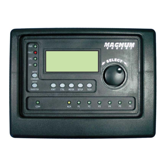
Operation Operation This section explains how to operate the inverter/charger using the ME-ARTR router. It also provides information on the LED indicators and the LCD display that are used to show the operational status of the inverter/charger. Front Panel The router’s front panel contains LED indicators and a LCD display for viewing system status, buttons to control system operation, and a rotary knob that enables you to locate and select system information and settings. -
Page 64: On/Off Buttons
Operation 5.1.3 ON/OFF Buttons • ON/OFF INVERTER: This button toggles the inverter function on and off. The green INV LED turns on and off with the button. • ON/OFF CHARGER: This button toggles the charger function on and off after it is actively charging. -
Page 65: Operating The Inverter/Charger
The ME-ARTR has four Home screens: a System Home screen, All PORTs Home screen, Individual PORTs Home screen, and an Accessory PORTs Home screen (see Figure 5-3). Each display shows pertinent information about any attached devices or accessories, as well as their current operating status. -
Page 66: Inverter Mode Status Messages
Operation System/Inverter Accessory Status Device Connected Device Status Status (first Acc port ) MS4024PAE Inverter Inverting FAULT FAULT Inverting Gen off 29.3VDC 20.0ADC 29.3VDC 20.0ADC System Home INV Home System PORT Screen Device Menu Heading System Home System Device Info Ports Voltage Menu... -
Page 67: Charger Mode Status Messages
Operation Inverter Standby appears on the LCD. The INV Inverter Standby (green) LED is on solid. All other LEDs are off. FAULT Settings/Info... Figure 5-6, Inverter Standby Mode • Inverter Standby (Inv Stby) – The inverter is on, but not actively providing power. However, it is monitoring the power requirement of the parallel system to determine when to activate and provide power to assist the master inverter. -
Page 68: Figure 5-10, Absorb Charging Mode
Operation Absorb Charging appears on LCD. PWR (green) LED Absorb Charging is on solid. CHG (green) LED is typically on solid, but FAULT may blink. FAULT (red) LED is off, and INV (green) LED could be on or off. Settings/Info... Figure 5-10, Absorb Charging Mode •... -
Page 69: Figure 5-14, Constant Current Mode
Operation Constant Current appears on LCD. PWR (green) and Constant Current CHG (green) LEDs are on solid. FAULT (red) LED is FAULT off, and INV (green) LED could be on or off. Settings/Info... Figure 5-14, Constant Current Mode • Constant Current (CCurrent) – The battery charger is delivering maximum current to the batteries (determined by the Max Charge Amps setting under the SETUP button’s 03C Battery Type: CC/CV menu). -
Page 70: Figure 5-17, Float Charging Mode
Operation CAUTION: During Equalizing mode, the batteries begin gassing and bubbling vigorously—which consumes water. Ensure each cell has adequate distilled water levels prior to equalizing, and add water as needed after equalizing. CAUTION: Ensure your batteries can be equalized. Only do so if permitted by your battery manufacturer or dealer. -
Page 71: Figure 5-19, Load Support Aac Mode
Operation Load Support AAC appears on LCD. PWR (green) Load Support AAC LED is on solid and CHG (green) LED blinks. FAULT FAULT (red) LED is off, and INV (green) LED is on solid. Settings/Info... Figure 5-19, Load Support AAC Mode •... -
Page 72: Secondary Scrolling Status Messages
Operation 5.3.3 Secondary Scrolling Status Messages These displays alternate with the inverter’s primary status to indicate other pertinent messages. Note: Depending on circumstances, the lighting sequence of the LED indicators may vary as there can be several secondary status messages scrolling at any one time. AC In –... -
Page 73: Figure 5-25, Inv Max Charge Time Mode
Operation Inv Max Charge Time appears on LCD. PWR (green) Inv Max Charge Time LED is on solid and CHG (green) LED is blinking. FAULT Settings/Info... Figure 5-25, Inv Max Charge Time Mode • Inv Max Charge Time – This display indicates the Max Charge Time safety feature was enabled because the Absorption charge was longer than the Max Charge: Time setting. -
Page 74: Figure 5-27, Reminder To Eq Mode
Operation Reminder to EQ appears on LCD. PWR (green) LED Reminder to EQ is on solid and CHG (green) LED blinks. FAULT Settings/Info... Figure 5-27, Reminder to EQ Mode • Reminder to EQ – This display indicates it is time to EQ the batteries. This occurs when the enabled SETUP: 01I Days to remind when to EQ setting has exceeded the # of days. -
Page 75: Fault Mode Messages
Operation 5.3.4 Fault Mode Messages The FAULT LED fl ashes and a fault status is displayed when an abnormal condition is detected. To determine which port has the fault, press the PORT button or rotate the SELECT knob until the FAULT LED turns solid. -
Page 76: Figure 5-33, Breaker Tripped Fault
Operation Breaker Tripped appears on the LCD and the FAULT Breaker Tripped (red) LED is on. The PWR (green), CHG (green), and FAULT INV (green) LEDs are off. Settings/Info... Figure 5-33, Breaker Tripped Fault • Breaker Tripped (Brk Trip) – The AC input breaker on the inverter/charger has opened due to excess current fl... -
Page 77: Figure 5-36, High Battery Fault
Operation High Battery appears on the LCD and the FAULT High Battery (red) LED is on. The PWR (green), CHG (green), and FAULT INV (green) LEDs are off. Settings/Info... Figure 5-36, High Battery Fault • High Battery (HighBatt) – The inverter has turned off because the battery voltage is at a very high level. -
Page 78: Figure 5-39, High Volts Ac Fault
Operation High Volts AC appears on the LCD and the FAULT High Volts AC (red) LED is on. The PWR (green), CHG (green), and FAULT INV (green) LEDs are off. Settings/Info... Figure 5-39, High Volts AC Fault • High Volts AC (High VAC) – This fault causes the AC input to be disabled due to a very high AC voltage (>145 VAC;... -
Page 79: Figure 5-42, Overcurrent Fault
Operation Overcurrent appears on the LCD and the FAULT Overcurrent (red) LED is on. The PWR (green), CHG (green), and FAULT INV (green) LEDs are off. Settings/Info... Figure 5-42, Overcurrent Fault • Overcurrent (Overcrnt) – This fault may be due to an excessive AC load, and causes the inverter to shut down to protect internal power components. -
Page 80: Figure 5-45, Tfmr Overtemp Fault
Operation Tfmr Overtemp appears on the LCD and the FAULT Tfmr Overtemp (red) LED is on. The PWR (green), CHG (green), and FAULT INV (green) LEDs are off. Settings/Info... Figure 5-45, Tfmr Overtemp Fault • Tfmr Overtemp (Tfmr OT) – This fault message displays when the transformer temperature is >266°F/130°C, causing the Thermal Cut-Out (TCO) sensor on the transformer to open. -
Page 81: Figure 5-47, Stackclock Fault
Operation 5.3.4.2 Stacking Fault Messages A fault condition may occur when multiple inverters are stacked in parallel—using the router— that is not possible on a single inverter installation. Refer to the following fault messages to help troubleshoot the inverters. StackClock Fault appears on the LCD and the FAULT StackClock Fault (red) LED is on. -
Page 82: Figure 5-50, Internal Bridge Fault
Operation 5.3.4.3 Internal Fault Messages The inverter continually monitors several internal components. If a condition inside the inverter occurs that does not allow proper operation, the inverter shuts down to protect itself. To clear these “internal” faults, the inverter requires an inverter reset. Remedy: Perform an inverter reset (see Section 6.2). -
Page 83: Led Indicator Guide
Operation 5.3.5 LED Indicator Guide Use the LEDs & LCD display to determining the operating status of your inverter/charger. Table 5-1, LED Indicator Guide Status Meaning 1) Inverter disabled; 2) Router’s in Power Save mode – press any button to activate LEDs; 3) No power to router (check router cable or power to inverter);... -
Page 84: Troubleshooting
Troubleshooting Troubleshooting If the router is not functioning correctly, use the following table to help fi nd solutions. Table 6-1, Router Troubleshooting Guide Symptom Possible Cause Solution Display shows Static electricity may Refresh Display: To refresh the display, unrecognizable letters have been discharged press and hold the METER button until the or symbols. -
Page 85: Troubleshooting Tips
Troubleshooting Troubleshooting Tips 6.1.1 Inverter Problems • Inverter turned on, green LED on inverter blinking, no output: Inverter is in Search mode. Either defeat Search mode, if not needed, or turn on loads greater than the 02A Search Watts setting. 6.1.2 Charger Problems •... -
Page 86: Performing An Inverter Reset
Troubleshooting Performing an Inverter Reset Press and hold the Power ON/OFF button (see Figure 6-1) for approximately fi fteen (15) seconds until the Charging/Inverting Status LED comes on and fl ashes. Once the fl ashing has begun, release the Power ON/OFF button. The Charging/Inverting Status LED goes off after the button is released. -
Page 87: Updating The Me-Artr Router's Firmware
Using a standard micro SD memory card, you can download and install updated fi rmware for your ME-ARTR router. Firmware updates are periodically available for download on our website (www.SensataPower.com). The web site also provides the ME-ARTR Firmware Update Instruction Sheet (PN:64-0092)—a detailed step-by-step procedure for successfully downloading and... -
Page 88: Using An Ags Module
IMPORTANT: The AGS must be a network version (ME-AGS-N) and must be connected and communicating with the ME-ARTR in order to set up and/or control the AGS. If the AGS is not communicating, “No AGS Present” appears when accessing the SETUP/04 AGS Setup or the CTRL/03 Gen Control menus, unless the TECH: 08 Show all Menus menu has been set to “Yes”. -
Page 89: Table 8-1, Software Differences Between Ags Versions
Using an AGS Module Table 8-1, Software Differences Between AGS Versions AGS Menu AGS Menu ME-AGS-N (Button: Menu) Selections/Settings Required CTRL: 03 Gen Control OFF, ON, AUTO ≥Vers 5.0 METER: 04 AGS Meters 04A AGS Status (Read Only) ≥Vers 5.0 04B DC Volts to AGS (Read Only) ≥Vers 5.0 04C Gen Run Time (Read Only) -
Page 90: Me-Ags-N Setup (With The Me-Artr)
Using an AGS Module: Setup ME-AGS-N Setup (with the ME-ARTR) To access the AGS SETUP menus, press and hold the METER button (~3 seconds) to display the System Home screen. From the System Home screen, press the PORT button, or rotate the SELECT knob to the port# where the AGS is connected (AGS Home screen), and then press the SETUP button. - Page 91 Using an AGS Module: Setup SETUP: 04A Gen Run DC Volts Menu This menu provides the option to start the generator when the battery voltage gets low, and to stop the generator either when the battery reaches a higher voltage level, or when the battery has been fully charged and goes into the Float Charge stage.
- Page 92 Using an AGS Module: Setup • Set Gen Run DC Volts (Stop Volts) – This setting will stop the generator when the battery voltage (on Terminals #3 & #4 of the AGS) increases to or above this setting continuously for the duration of the Set VDC Delay Times (Stop Delay) setting. To allow the battery bank to go through a full Bulk and Absorption charge, this setting should be set to Float (Silent).
- Page 93 Info: Ensure the router’s clock is correct. Refer to Section 3.3.4 for guidance on setting the time on the router clock. The ME-ARTR’s clock is powered from the inverter through the remote cable. If the ME-ARTR or inverter loses power, the clock loses the correct time and must be reset.
- Page 94 Using an AGS Module: Setup Why would I use Gen Run AC Amps? This feature is designed to prevent the battery from being heavily discharged by monitoring the battery current used to power the inverter loads (shown in AC amps). When the AC current exceeds the Start AC Amps setting, a generator autostart is initiated.
- Page 95 Using an AGS Module: Setup Info: The METER: 05 BMK Meters/05A BMK SOC meter must have a valid SOC number for the 04D Gen to determine when to start and stop based on the battery SOC. Under the METER/05 BMK Meters/05A BMK SOC menu, Think’n, No Comm, or any BMK fault (i.e., Factory Fault, Power-up Fault, or Unknown Fault ##) are not valid SOC numbers.
- Page 96 Using an AGS Module: Setup How does the Gen Run Temp feature work? When the temperature around the remote temperature sensor (based on the METER: 04D AGS Temp display) increases to the Gen Run Start Temp setting, the generator immediately starts and runs based on the Gen Temp Run Time setting.
- Page 97 The generator does not try to autostart until the Quiet Time stop setting has been reached and an autostart condition is once again satisfi ed. Info: The ME-ARTR contains a real time clock that must be set for proper operation of the SETUP: 04G Gen Quiet Time menu feature.
- Page 98 Using an AGS Module: Setup Why would I use Quiet Time? Quiet Time is used when there are park rules or local regulations that prevent generators from running (e.g., noise requirements during sleep hours). If there are no local rules or regulations, you may not want to use Quiet Time—which would allow the generator to run at any time in a 24-hour period.
- Page 99 Once the start command is initiated, the generator starts and runs to help it remain operational and to allow the generator’s starting battery to be charged. Info: The ME-ARTR contains a real time clock that must be set for proper operation of the SETUP: 04H Gen Exercise menu feature.
- Page 100 Using an AGS Module: Setup Example of a Gen Exercise Scenario: Under SETUP: 04H Gen Exercise menu, set to: Start Gen Days = 3, then set Start Time = 8:30AM, and then set Run Time = 1.0 Hours. Under CTRL: 03 Gen Control, set to AUTO. First required condition: The Days Since Run timer must have accumulated to at least 3 days (Start Gen Days = 3).
- Page 101 Using an AGS Module: Setup SETUP: 04J Gen 100% SOC Menu This setting allows the AGS to autostart the generator at a pre-selected time of day—whenever a set number of days have passed since the battery bank has been charged to 100% SOC. Info: The optional Battery Monitor Kit (ME-BMK or ME-BMK-NS) must be installed and enabled to use the Gen 100% SOC Start feature.
-
Page 102: Me-Ags-N Functional Tests Using The Me-Artr
01 AC In Control menu to Auto Connect. This ensures the generator—once autostarted— will connect and charge the battery. Info: The ME-ARTR contains a real time clock that must be set for proper operation of the SETUP: 04J Gen 100% SOC Start feature. -
Page 103: Me-Ags-N Operation/Monitoring (With The Me-Artr)
CTRL: 03 Gen Control menu is used to activate the generator either manually or automatically. Press the CTRL button on the ME-ARTR router to access the 01 AC In Control and the 03 Gen Control menus. -
Page 104: Enabling The Me-Ags-N
AGS immediately begins to monitor for any active autostart/autostop settings again. 8.2.3 Monitoring the AGS using the ME-ARTR The ME-ARTR router has additional METER button menus that are helpful for the proper operation and monitoring of your AGS system. 8.2.3.1 ME-ARTR Router’s AGS METER Menus Press router’s METER button and rotate the SELECT knob to view the following read-only menus. - Page 105 Using an AGS Module: Operation METER: 04B DC Volts to AGS This read-only menu displays the DC voltage measured at Terminal #3 and Terminal #4 of the AGS module. This menu is useful in setting up the voltage start for the AGS, and for troubleshooting its operation.
- Page 106 Terminal 2 of the AGS, which could be either by autostarting the generator (including from a previous exercise run), or manually starting the generator (using the ME-ARTR). Info: When the DIP switch inside the AGS is set to “2-Wire Standby Mode”, which does not require the gen run sense signal to be present on Terminal 2 of the AGS, the Since Run Days timer will not be reset to zero.
-
Page 107: Starting And Stopping The Generator
Starting and Stopping the Generator The generator can be manually started/stopped, as well as autostarted/autostopped using the available settings from your ME-ARTR. To autostart/autostop the generator: In order for the generator to autostart/autostop, one or more of the following autostart/autostop conditions must be pre-set (see Section 8.1):... -
Page 108: Me-Artr Router's Ags Menu Maps
Using an AGS Module: Operation 8.2.5 ME-ARTR Router’s AGS Menu Maps This section provides the AGS menu maps available from your router. Refer to Appendix A in the back of this manual for a glossary of abbreviations that may appear on the router’s LCD display. -
Page 109: Figure 8-3, Ags Setup Menu Maps (Section 1)
Using an AGS Module: Operation Note: The AGS-N SETUP menus are accessed via the System Home screen and PORT button; or, by pressing the SETUP button and rotating to the 04 AGS Setup menu, and then pressing the SELECT knob. Refer to the procedures below to access these menu items via the AGS Home screen. Inverting System Home Screen –... -
Page 110: Figure 8-4, Ags Setup Menu Maps (Section 2)
Using an AGS Module: Operation AGS SETUP menu continued from previous page Set Time to Topoff Set Gen Quiet Time 04G Gen Quiet Time Battery before Quiet Begin Quiet= 7:00PM Begin Quiet= 7:00PM Time= 30 Minutes End Quiet =10:00AM End Quiet =10:00AM edit AGS SETUP edit AGS SETUP... -
Page 111: Me-Ags-N Router Status Messages
Using an AGS Module: Operation 8.2.6 ME-AGS-N Router Status Messages A status message may be an operational or fault message. Access the AGS status menu (METER: 04A AGS Status menu) to view the AGS’s current operating status. This menu is important when determining if the AGS is working correctly, or for troubleshooting an AGS installation. -
Page 112: Table 8-4, Ags Router Start Statuses
Using an AGS Module: Operation 8.2.6.2 AGS Router Start Statuses The following “Start” statuses identify the condition that autostarted the generator. If you determine the autostart condition occurred sooner than expected (or didn’t want this autostart condition), refer to Section 8.1 to change (or defeat) the autostart setting. Table 8-4, AGS Router Start Statuses Status Description... -
Page 113: Table 8-6, Ags Default Settings On Me-Artr
Section 8.3 “ME-AGS-N Router Troubleshooting (with the ME-ARTR)”. • When the 03 Gen Control setting on the ME-ARTR is in the OFF position, all generator autostart functions are disabled and the AGS’s STATUS indicator will also be off. -
Page 114: Me-Ags-N Router Troubleshooting (With The Me-Artr)
When an AGS fault is detected, and the ARTR’s FAULT LED comes on, the fault status is displayed on the LCD screen. Figure 8-5 is an example of how fault messages appear on the ME-ARTR. Use the ARTR’s LCD screen and the information in this section to identify and correct the issue. -
Page 115: Resolving Ags Faults Using Your Router
Using an AGS Module: Troubleshooting 8.3.2 Resolving AGS Faults using your Router For the nine faults that follow, refer to the Remedy immediately following the list. • Fault Amp – The generator failed to autostart and run per the 04C Gen Run AC Amps menu’s start parameters. - Page 116 Fault Test – The generator failed to autostart and run after the red TEST button is pressed on the AGS module. Note: The ME-ARTR does not provide a “test” selection, instead it can be set to manually turn the generator on and off, which can be used to test the generator wiring to the AGS.
-
Page 117: Using A Bmk
Using a BMK: Setup Using a BMK This section discusses how to set up, operate and troubleshoot the BMK using the ME-ARTR router. Refer to the mini-index below to direct you to the appropriate section. ME-BMK Setup (with the ME-ARTR) -
Page 118: Me-Bmk Operation/Monitoring (With The Me-Artr)
This section explains how the ME-BMK (Battery Monitor kit) battery monitor works, and how to use the ME-ARTR to obtain battery bank information. It also covers the various LCD displays that are related to the battery monitor and the status of the sense module’s LED indicator. -
Page 119: Bmk Meter Menu Items (With Me-Artr)
From the BMK Home screen, press the METER button, and then turn the SELECT knob on the ME-ARTR router to access the different meters that determine the status of the battery system. Info: If multiple BMKs are connected, the System Home screen displays information from the BMK connected to the LOWEST numbered port. - Page 120 Using a BMK: Operation/Monitoring The range is 0% to 100%, where 100% is a fully charged battery and at 0% the battery is completely discharged. When the BMK sense module is fi rst connected, the display will show “Think’n”, to indicate that the SOC reference point is being calculated. After the batteries are fully charged, the display will change from “...
-
Page 121: Me-Artr Router's Bmk Menu Maps
Figures 9-2, 9-3 & 9-4 are a complete overview of the battery monitor settings and information displays available from the ME-ARTR router’s SETUP and METER menus. Refer to Appendix A in the back of this manual for a glossary of abbreviations that may appear on the router’s LCD display. -
Page 122: Figure 9-3, Bmk Meter Menu Maps (All Ports)
Using a BMK: Operation/Monitoring METER ALL Ports METER Displays: 03 Timers 05A BMK SOC 05B DC Volts-BMK 04 AGS Meters 1 ---- 2 ---- 3 ---- 1 ---- 2 ---- 3 ---- 05 BMK Meters 4 Thnk 5 ---- 6 ---- 4 27.4 5 ---- 6 ---- Select METER... -
Page 123: Bmk Status Messages (With The Me-Artr)
Using a BMK: Operation/Monitoring 9.2.4 BMK Status Messages (with the ME-ARTR) A status message may be an operational or fault message. Access the BMK Home screen (see INFO Section 9.1 to access) to view the BMK’s current operating status. The status is important when determining if the BMK is working correctly, or for troubleshooting a BMK installation. -
Page 124: Me-Bmk Troubleshooting (With The Me-Artr)
When a BMK fault is detected, the ARTR’s FAULT LED (red) comes on and the fault status is shown on the LCD display. Figure 9-5 is an example of how fault messages appear on the ME-ARTR. Use the ARTR’s LCD screen and the information in this section to identify and correct the issue. -
Page 125: Attaching A Remote Control
Attaching a Remote Control 10.0 Attaching a Remote Control A remote control (ME-ARC or ME-RC) can be connected to the router and used in a different location to assist with monitoring your system. Only one remote control can be used, and it must be connected directly to one of the router ports and programmed (per SETUP: 06 RC Setup menu) to indicate which port it is monitoring. -
Page 126: Using An Acld
02A Search Watts Sensitivity setting should be turned to OFF (see page 26). 11.2 Monitoring the ACLD using the ME-ARTR This section covers the menus under the ME-ARTR’s METER button that enable you to monitor the ACLD controller’s operation. 11.2.1 ME-ARTR’s ACLD METER Button Menus Press the ME-ARTR’s METER button, rotate the SELECT knob to 06 ACLD Meters, and then press... -
Page 127: 11.2.2 Me-Artr Router's Acld-Specifi C Tech Menus
The diagram below is a complete overview of the ACLD information displays available from the ME-ARTR router’s METER button ACLD menu. Refer to Appendix A in the back of this manual for a glossary of abbreviations that may appear on the router’s LCD display. -
Page 128: 11.2.4 Acld Router Status Messages
ACLD is working correctly, or for troubleshooting an ACLD installation. Note: “Fault statuses” indicate that the ACLD is not operating as intended. Refer to Section 11.3.2 “Resolving ACLD Faults using the ME-ARTR” to identify and diagnose the problem. 11.2.4.1... -
Page 129: 11.3 Acld Troubleshooting Using The Me-Artr
Meters/06A ACLD Status menu to view the fault status. Figure 11-2 is an example of how ACLD fault messages appear on the ME-ARTR router. Use the router’s LCD screen, your ACLD owner’s manual, and the information in this section to identify and correct the issue. -
Page 130: Using A Pt Charge Controller
12.1 Setting Up the PT Controller using the ME-ARTR Use the ME-ARTR’s SETUP button to identify a battery type and the Absorb Done, PT Max Charge Rate/Time, Bulk Start, PT Relay VDC, PT Relay SOC, PT Alarm and PT PowerSave settings for your PT controller. - Page 131 Using a PT Controller: Setup Max Chg Rate – Sets the maximum charge amperage allowed to charge the batteries during the CC/CV charge stage. The range of settings (20-990 ADC) are provided to limit the charge current to the battery bank, which helps prevent battery overheating caused by charging at too high a charge rate.
-
Page 132: Figure 12-1, Cv Charge Done Time/Amps (Pt Controller)
Using a PT Controller: Setup Info: The ME-BMK battery monitor is required if the CV Chg Done Amps setting is used. The CV Chg Done Amps setting relies on the METER: 05C DC Amps-BMK value to determine when to transfer out of the Constant Voltage charge mode. Info: Setting the CV Chg Done Amps value to zero keeps the charger in the Constant Voltage charge mode until the Max CC/CV Time setting (under SETUP: 07A Battery Type: CC/CV) is reached. -
Page 133: Figure 12-2, Hold Cv Charge Volts (Pt Controller)
Using a PT Controller: Setup Hold CV Chg Volts – This setting holds the battery voltage at the CV Charge Volts setting. This is for a system that requires a constant charge voltage to be present at all times (see Figure 12-2). CV Stage CC Stage Charge Stage... -
Page 134: Figure 12-3, Multi-Stage Charging (Pt Controller)
Using a PT Controller: Setup First Stage Third Stage Second Stage Charge Stage Bulk Charging PT Status Absorb Charging Float Charging Max Charge Absorb Amps Volts Float Volts Absorb Done (Time, Amps or SOC) Current Voltage TIME Figure 12-3, Multi-Stage Charging (PT Controller) •... - Page 135 Using a PT Controller: Setup Info: The ME-BMK battery monitor is required if the Absorb Done Amps setting is used. The Absorb Done Amps setting relies on the METER: 05C DC Amps-BMK value to determine when to transfer out of the Absorption charge stage. ◊...
- Page 136 Using a PT Controller: Setup CAUTION: If using “OFF”, the batteries can be held at a high voltage for an extended time. Monitor the batteries to ensure they are not overcharged. Info: If the time the charger has been in Bulk, Absorption, or EQ charge modes exceeds the Max Charge Time setting, the “PT Max Charge Time”...
- Page 137 Using a PT Controller: Setup Note: If “CC/CV Controlled” displays on this menu’s screen, you will not be able to adjust the settings as “CC/CV” has been selected as the battery type from the 07A Battery Type menu. Info: The METER: 05A BMK SOC menu’s meter must have a valid SOC number for the Bulk Start –...
- Page 138 Using a PT Controller: Setup • 07F PT Relay SOC – When SOC is selected from the CTRL: 05B PT Aux Relay menu, the Aux Relay in the PT controller can be programmed to engage or disengage based on the SOC percentage of your battery bank using the following settings.
-
Page 139: 12.2 Operating/Monitoring The Pt Controller Using The Me-Artr
Range: OFF, 1-60 Min (1-min increments) 12.2 Operating/Monitoring the PT Controller using the ME-ARTR This section provides the PT menus under the ME-ARTR’s CTRL and METER buttons that determine how to control and operate the charge controller. 12.2.1 Operating the PT Charge Controller The charge mode is automatically activated and begins when acceptable PV power is connected to the PV input of the controller. - Page 140 Using a PT Controller: Operation/Monitoring • Start Float – This selection restarts the Float charge cycle from any stage in the charge cycle as long as the controller is actively charging. Info: The Start Float selection automatically returns to the Multi-Stage setting once the PT controller status displays as “Float Charging”...
- Page 141 Using a PT Controller: Operation/Monitoring • DISENGAGED – Manually forces the PT Aux Relay contacts to stay disengaged. When the PT Aux Relay is disengaged, the COM to N.O. contact is open, and the COM to N.C. contact is closed. This setting can be used to manually control the device connected to the PT Aux Relay, or can be used to test the PT Aux Relay’s operation.
-
Page 142: 12.2.2 Monitoring The Pt Charge Controller
12.2.2.1 ME-ARTR Router’s PT Controller METER Menus Press the ME-ARTR router’s METER button, rotate the SELECT knob to the 07 PT Meters menu, and then press the SELECT knob to access the 07 PT Meter read-only menus. Rotate the SELECT knob to view the various PT meters. - Page 143 Using a PT Controller: Operation/Monitoring There are eight different PT Power statuses and two PT Relay statuses that can display (refer also to Figure 12-5, and Tables 12-3 and 12-5). Power Status: PT Relay Status: • Limit: Above VDC • Disengaged •...
- Page 144 12-6 also provides an example of how to navigate the PT Data matrix. Note: If there is no PT data, then “No Data Recorded” displays on the ME-ARTR when you select this menu. PT data is continually updated for the current day (i.e., Today’s data).
- Page 145 Menus option, then “Not Stacked” will display. 12.2.2.2 ME-ARTR Router’s PT-specifi c TECH Menus Press the ME-ARTR’s TECH button, and rotate the SELECT knob to access: TECH: 01 Temperatures (rotate SELECT knob until PT Temps displays) • 01F PT Temps – Displays the temperature of the attached BTS, and the PT controller’s FETs and Inductor.
-
Page 146: 12.2.3 Pt Charge Controller Menu Maps
Figures 12-4 through 12-8 are a complete overview of the PT settings and information displays available from the ME-ARTR router’s CTRL, METER, and SETUP menus. Refer to Appendix A in the back of this manual for a glossary of abbreviations that may appear on the router’s LCD display. -
Page 147: Figure 12-5, Pt Charge Controller Meter Menu Map
Using a PT Controller: Operation/Monitoring METER 07A PT Status 07B Aux Relay 07C PT Volts 05 BMK Meters [PT Status] Status:[RelayStatus] PV Volts: 147.0 VDC 06 ACLD Meters 07 PT Meters [Power Status] Bat Volts: 14.4 VDC View PT METER ALL Select METER View... -
Page 148: Figure 12-6, Pt Charge Controller Data History Matrix Menu Map
Using a PT Controller: Operation/Monitoring Accessing System PT Data History Rotate SELECT knob to Rotate SELECT knob to 07H PT Data access PT data for access subsequent Press SELECT button additional connected system data for past to see Log controllers (C01-C07). days 002-255. -
Page 149: Figure 12-7, Pt Charge Controller Setup1 Menu Map
Using a PT Controller: Operation/Monitoring Figure 12-7, PT Charge Controller SETUP1 Menu Map Page 140 © 2017 Sensata Technologies... -
Page 150: Figure 12-8, Pt Charge Controller Setup2 Menu Map
Using a PT Controller: Operation/Monitoring Continued SETUP 07E PT Relay VDC 07F PT Relay SOC 07G PT Alarm 07H PT Power Save x7 =20.0V/ 10secs Display = =20.0V/ 10sec Engage SOC = 50% =28.0V/ 10sec Disengage SOC =100% =28.0V/ 10secs View PT SETUP View... -
Page 151: 12.2.4 Pt Charge Controller Router Status Messages
Note: “No sun” is based on low PV voltage and no effective power (i.e., nighttime). Unknown Status This status message displays when the inverter/charger has sent a status code that cannot be determined by the ME-ARTR router. [UnkS ##] 12.2.4.2 PT Router Relay Statuses The following “Relay”... -
Page 152: Table 12-4, Pt Router Fault Statuses
Refer to Section 12.3.2 for help in diagnosing/resolving the problem. Note: Fault codes (example: “F12”) listed below only appear on the PT’s LCD display to identify the particular PT fault. These codes do not appear on the ME-ARTR router’s LCD display. Table 12-4, PT Router Fault Statuses... -
Page 153: Table 12-5, Pt Router Charge Modes
4% or greater battery voltage difference from the master controller. Note: The controller continues to run with this fault. Unknown Fault ## The PT controller turned off because the PT controller has sent a fault code that cannot be determined by the ME-ARTR router. 12.2.4.4 PT Router Charge Modes The following Charge Modes show the status of the controller’s charger. -
Page 154: Table 12-6, Pt Router Power Statuses
Using a PT Controller: Operation/Monitoring 12.2.4.5 PT Router Power Statuses The following “Power” statuses show the status of the controller’s Power Point Tracking. Note: The power status codes (example: “P04”) listed below only appear on the PT’s display to identify the particular PT power status. Table 12-6, PT Router Power Statuses Status Description... -
Page 155: 12.3 Pt Controller Troubleshooting Using The Me-Artr
12.3.1 PT Controller Fault Message Screens When a PT fault is detected, the ME-ARTR’s red FAULT LED lights and the fault status is displayed on the LCD screen (see Figure 12-9 example). Use the router’s LCD screen and the information in this section to identify and correct the issue. - Page 156 Using a PT Controller: Troubleshooting • BTS Open-PT – The BTS has opened or is no longer connected. This fault causes the BTS to show 305°F/ 152°C on the TECH: 01F PT Temps display. With a defective or disconnected BTS, there is no temperature compensation applied to the battery charging voltage.
- Page 157 Using a PT Controller: Troubleshooting • High Bat VDC-PT – High voltage (≥68 VDC) has been detected on the battery input terminals (i.e., BAT+ to BAT-). Remedy: Check the voltage on the battery terminals. High voltage can be caused by an incorrect connection of the PV array to the battery terminals, or the battery bank being charged by an external means and the voltage is >68 VDC (including ripple voltage).
- Page 158 Using a PT Controller: Troubleshooting • Int Power-PT – The internal power control circuity reached its protection limits. Remedy: When this fault condition occurs, the controller shuts down to help protect itself. Press the RESET pushbutton for one second to turn the controller on and to verify the fault has cleared.
- Page 159 Using a PT Controller: Troubleshooting • Stack ComLost-PT – The controller was previously communicating on the network, but now it is no longer receiving any communications from the Magnum inverter or from another controller. Note: The controller continues to run with this fault. Remedy: This fault can be caused by: 1.
-
Page 160: Appendix A - Router Display Abbreviations
Appendix A – Router Display Abbreviations Appendix A – Router Display Abbreviations Use the table below to identify the abbreviations that may appear on your router’s LCD display. Table A-1, Abbreviations on Router Display SHORT ABBREV. (8 char.) MINI ABBREV. (4 char.) FULL NAME (DEVICE) Absorb (PT) Absorb Absorb Charging... - Page 161 Appendix A – Router Display Abbreviations Router Display Abbreviations (Cont.) SHORT ABBREV. (8 char.) MINI ABBREV. (4 char.) FULL NAME (DEVICE) Disengage (PT) Empty No Inverter Found Engage (PT) EQ (PT) Equalize EQ Charging (PT) Equalize Equalizing ExtInput External Input (AGS) FacFault FacF Factory Fault (BMK)
- Page 162 Appendix A – Router Display Abbreviations Router Display Abbreviations (Cont.) SHORT ABBREV. (8 char.) MINI ABBREV. (4 char.) FULL NAME (DEVICE) High VAC High Volts AC TS Hot (AGS) Hrs or HH/Min or MM/Sec H, M, s Hours/Minutes/Seconds Inactive Inac Inactive (ACLD) Ind Overtemp (PT) Int Brdg...
- Page 163 Appendix A – Router Display Abbreviations Router Display Abbreviations (Cont.) SHORT ABBREV. (8 char.) MINI ABBREV. (4 char.) FULL NAME (DEVICE) OverTemp Overtemp P1-P6 Port 1-6 Port# 1 Accessory Personal Identifi cation Number PT-100 Controller PwrFault PwrF Power-up Fault (BMK) QuietTme Quiet Time (AGS) Remote Control...
- Page 164 Appendix A – Router Display Abbreviations Router Display Abbreviations (Cont.) SHORT ABBREV. (8 char.) MINI ABBREV. (4 char.) FULL NAME (DEVICE) Unknown ## (PT) Unknown Fault ## (PT) UnkP ## Unknown Power ## (PT) UnkS ## Unknown Status ## (PT) Unk?##? ?##? Unknown ?##? (AGS)
-
Page 165: Appendix B - Router Feature To Inverter Compatibility
Appendix B – Compatibility Matrix Appendix B – Router Feature to Inverter Compatibility When the ME-ARTR is released with new software, some of the features/functionality may not be available in an inverter or networked accessory with an earlier software level. In this case, the advanced setting is not recognized and will not function. - Page 166 Appendix B – Compatibility Matrix FEATURES/SETTINGS Model/ Default Level Menu Selections/ Setting Main Menu Required Heading/Item Adjustments Range 03A Charge Time 03 Timers Read Only display ≥Level 1 Read Only 03B Days Since 04A AGS Status 04B DC Volts to AGS 04C Gen Run Time 04 AGS 04D AGS Sensor Temp...
- Page 167 Appendix B – Compatibility Matrix FEATURES/SETTINGS Model/ Default Level Menu Selections/ Setting Main Menu Required Heading/Item Adjustments Range PowerSave= OFF, 1-60 min 15 Min 01C Power Save Port LEDs = Auto, OFF Auto ≥Level 1 01D Temp Display Fahrenheit, Celsius Fahrenheit 01E Viewing Ports Auto Scroll = OFF, 1-60 sec...
- Page 168 Appendix B – Compatibility Matrix FEATURES/SETTINGS Model/ Default Menu Selections/ Level Main Setting Menu Heading/Item Adjustments Range Required AGM1, AGM2, Flooded, GEL ≥Level 1 Flooded Absorb = 12.0-16.0V* 12.0V Float = 12.0-16.0V* ≥Level 3 13.2V Custom EQ Volts = 12.0-16.0V* 14.0V EQ Time = 0.1-25.5Hrs 4.0 Hrs...
- Page 169 Appendix B – Compatibility Matrix FEATURES/SETTINGS Model/ Default Level Menu Selections/ Main Setting Menu Required Heading/Item Adjustments Range Start AC Amps = OFF, 5-60A Stop AC Amps = 4-59A 04C Gen Run AC ≥Level 4 Amps Start Delay = 0-127s, 1-127m 120 sec Stop Delay = 0-127s, 1-127m 120 sec...
- Page 170 Appendix B – Compatibility Matrix FEATURES/SETTINGS Model/ Default Level Menu Selections/ Main Setting Menu Required Heading/Item Adjustments Range AGM1, AGM2, Flooded, GEL ≥Level 1 Flooded Absorb = 12.0-16.0V* 12.0V Float = 12.0-16.0V* 13.2V ≥Level 3 Custom EQ Volts = 12.0-16.0V* 14.0V EQ Time = 0.1-25.5Hrs 4.0 Hrs...
- Page 171 Appendix B – Compatibility Matrix FEATURES/SETTINGS Model/ Default Menu Selections/ Level Main Setting Menu Required Heading/Item Adjustments Range ON Volts = 8.0-17.0* 10.0V ON Delay = 0-127s, 1-127m 10 Secs 07 PT 07G PT Alarm ≥Level 4 OFF Volts = 8.0-17.0* 14.0V Setup (Cont.)
-
Page 172: Appendix C - Using The Router With Non-Stacked Inverters
Appendix C – Using the Router with Non-stacked Inverters Appendix C – Using the Router with Non-stacked Inverters Using Router to Control Multiple Unconnected Inverters The router can be used to control multiple Magnum inverters—under certain conditions—that are not connected in parallel (i.e., non-stacked). Each connected inverter must be the same model (i.e., MS4024 and another MS4024), each inverter must be connected to the same battery bank, and because the output of all the inverters are not in-phase with each other, the AC outputs must be isolated from each other. -
Page 173: Appendix D - Using The Me-Artr In An Ac Coupled Application
The MS-PAE Series inverter is optimized to work with Magnum Energy’s MicroGT500 grid-tie inverter to regulate battery voltage. During a utility power interruption, if the battery voltage begins to rise above the absorb voltage, the output frequency of the MS-PAE Series will start shifting down. -
Page 174: Appendix E - Warranty And Service Info
Note: You can extend the normal one-year warranty on the ME-ARTR to fi ve years simply by ordering it with and installing it on a Magnum Energy MP or MMP panel system. To be eligible for the 5-year warranty extension, a proof-of-purchase is required at the time of repair/service showing that the ME-ARTR and the MP or MMP panel system were purchased at the same time. -
Page 175: Index
Index Index Symbols AGS CTRL Menus AC In Control 14, 15, 16, 27, 55, 58, 63, ###% 114 93, 94, 164 Gen Control 14, 16, 55, 77, 79, 87, 88, 91, 93, 94, 95, 96, 97, 98, 102, Absorb/CV Done 20 107, 116 Absorb Done 16, 20, 26, 29, 34, 37, 38, AGS Fault Statuses... - Page 176 Index B (Cont.) A (Cont.) BMK Fault Statuses 114 Start Time 92 Factory Fault 114 Gen Exercise 23, 90, 91, 103, 106 Power-up Fault 114 Run Time 90 Unknown Fault 114 Start Gen Days 90 BMK Meters 20, 25, 29, 38, 86 Start Time 90 BMK Operational Statuses 114 Gen No-Load Time 91, 102...
- Page 177 Index D (Cont.) F (Cont.) DC Volts to ReBulk 42, 62 Front Panel (Cont.) LED Indicators 54, 63, 130 DC Volts to Recharge 34, 36, 62 Menu buttons Default Settings AGS 104 CTRL 2, 14, 16, 55, 79, 93, 94, 95, 98, 116, 130 Inverter/Charger 47 METER 12, 18, 22, 24, 44, 55, 75, 81,...
- Page 178 Index P (Cont.) PT CTRL Menus LCD Display 1, 6, 12, 13, 15, 39, 48, 54, 55, 57, 58, 60, 74, 75, 99, 112, 115, PT Alarm 132 118, 127, 131, 137, 143, 151 FAULT 132 LED Indicators 54, 63, 130 OFF 132 Link PT Charge 26 ON 132...
- Page 179 Index P (Cont.) P (Cont.) PT Menu Maps (Cont.) PowerSave PT Display 130 SETUP 140, 141 PT Alarm 121, 129, 132 PT METER Menus 133–136 PT Chg Ctrl 130 Aux Relay 134 PT Max Charge 126–127 Clear PT Data History 136 PT Relay SOC 121, 129 Ground Fault 135 PT Relay VDC 121, 128, 132...
- Page 180 Index S (Cont.) System Clock 23 Warranty 165 System Fault Messages 66 Wiring 10, 11, 66, 70, 72, 76, 93, 107, 1 AC Backfeed Mode 66 Aux Relay 11 AC Overload Fault 66 Breaker Tripped Fault 67 Dead Battery Charge Fault 67 FET Overload Fault 67 High Battery Fault 68 High Battery Temperature 68...
- Page 181 NOTES...
- Page 182 Magnum Energy Products Manufactured by: Sensata Technologies www.SensataPower.com ME-ARTR Owner’s Manual (PN: 64-0091 Rev A)
Need help?
Do you have a question about the ME-ARTR and is the answer not in the manual?
Questions and answers