Sign In
Upload
Manuals
Brands
Maeda Manuals
Construction Equipment
MK0003
Maeda MK0003 Manuals
Manuals and User Guides for Maeda MK0003. We have
1
Maeda MK0003 manual available for free PDF download: Service Manual
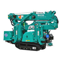
Maeda MK0003 Service Manual (348 pages)
MINI-CRAWLER CRANE
Brand:
Maeda
| Category:
Construction Equipment
| Size: 36 MB
Table of Contents
Table of Contents
3
Item Page
4
Overview
9
Outside Drawing
10
Standard Specifications
10
Engine and Electric Motor Specifications
11
Dimensional Drawing of Outrigger Width
12
Principle Specification List
13
Standard Specifications
13
Engine and Electric Motor Specifications
15
Working Radius/Lifting Height
17
Rated Total Load Chart
26
Crane Standard Pressure and Operating Time Table
27
Crane
28
Power Transmission Schematic Diagram
28
Structure and Maintenance Procedure
29
Hydraulic Circuit Diagram
29
Hydraulic Piping Diagram
35
Crane Rotating Part
35
Hose Guide
36
Control Line a
41
Control Line B
43
Travel Line
45
Outrigger Line
47
Line
49
Oil Cooler
50
Check Valve
51
Hydraulic Tank
57
Air Breather Assembly
59
Return Filter
60
Engine Assembly
61
Engine Specifications
61
Engine Appearance
62
Components of Engine
64
Fuel
64
Appropriate Use
64
Biodiesel Fuel
65
Diesel Fuel Standards
65
Fuel Feed to Fuel System
66
Maintenance and Inspection
67
Trouble Shooting
68
Fuel Piping
72
Fuel Line
72
Fuel Tank Assembly
74
Fuel Sender
75
Engine Accessories
76
Hydraulic Pump
79
Pump Assembly
79
Appearance and Specifications (Standard Pump)
80
Internal Structure
81
Operating Principles
82
Failure Cause and Countermeasure
84
Travel Control Valve
85
Appearance and Specifications
85
Internal Structure
86
Inspection and Adjustment
87
Failure Cause and Countermeasure
88
Traveling Motor
89
Appearance and Specifications
89
Internal Structure
90
Operating Principles
91
Operating Principles
92
Reducer
92
Hydraulic Motor
93
Hydraulic Valve (Counter-Balance Valve)
94
Parking Brake
95
Precautions for Use
96
Failures and Countermeasures
98
Crane Control Valve
99
Outside Drawing
99
Overview
100
Hydraulic Circuit Diagram
101
Actions of each Section
102
Failure Cause and Countermeasure
109
Outrigger Select Valve
110
Appearance and Specifications
110
Internal Structure
112
Inspection of Valves
113
Methods for Operation Adjustment
114
Outrigger Change-Over Switch
115
Rotary Joint
116
Appearance and Specifications
116
Internal Structure
118
Rotary Brush
119
Hook
125
Inspection of Hook
125
Boom
126
Main Boom
126
Jib
129
Jib Head
131
Telescopic and Derrick Cylinders
132
Main Telescopic Cylinder
132
Jib Telescopic Cylinder
134
Jib No.1 Telescopic Cylinder
136
Jib No.2 Telescopic Cylinder
138
Jib Telescopic Cylinder Hydraulic Schematic Diagram
140
Counter Balance Valve (for Telescopic and Derrick Cylinders)
141
Failure Cause and Countermeasure
141
Structural Drawing
141
Working Diagram
142
Sequence Valve (for Telescopic Cylinder)
143
Structural Drawing
143
Working Diagram
143
Mechanical Check Valve (for Telescopic Cylinder)
144
Main Derrick Cylinder Assembly
145
Main Left-Hand Derrick Cylinder
147
Main Right-Hand Derrick Cylinder
149
Jib Derrick Cylinder Assembly
151
Jib Derrick Cylinder
152
Slewing Device
154
Outside Drawing
154
Tolerance of Looseness Height of Slewing Bearing
155
Internal Structure and Specifications of Reduction Gears
156
Appearance and Specifications of Hydraulic Motor
157
Internal Structure of Hydraulic Motor
158
Failure Cause and Countermeasure of Slewing Device
159
Outrigger
160
Appearance of Outrigger on Rear Right Side
160
Appearance of Outrigger on Front Right Side
162
Appearance of Outrigger on Front Left Side
164
Appearance of Outrigger on Rear Left Side
166
Outrigger Cylinder
168
Appearance and Specifications
168
Internal Structural Drawing
170
Double Pilot Check Valve
172
Electric Circuit Diagram
173
Electric System
174
Wire Harness of Machine Body
174
Wire Harness of Machine Body
176
Control Unit Assembly
177
Control Assembly
179
Controller
179
Monitor
184
Structure of Monitor Screen
184
User Mode
197
Service Mode
204
List of Data Logger Display Contents
208
List of Controller Input Monitoring
209
List of Controller Analog Input / Output Monitoring
210
List of Error Codes
211
Procedure for Disassembling and Reassembling Boom
212
Removing Wire Harness Connectors
212
Removing Hydraulic Hoses
213
Preparing Hoisting Accessories
214
Removing the Rod Pin and Foot Pin of Main Derricking Cylinder
215
Removing the Link Assembly
216
Disassembling the Main Boom
217
Removing the Main Boom no
218
Removing the Telescopic Cylinder
219
Adjusting the Main Boom Extending/Contracting Wire Ropes
220
Assembling Procedure for Main Boom
220
Disassembling the Jib 20.8.1 Removing the Jib no
222
Removing the Jib no
223
Removing the Telescopic Cylinder
224
Disassembling Procedure for the Machine with Optional Winch
225
Removing the Winch Wire
226
Removing the Winch Hydraulic Hose
227
Procedure for Disassembling the Vehicle Body
228
Procedure for Disassembling the Outrigger Top and Inner Boxes
228
Removal of Electric Motor Unit
230
How to Remove and Mount a Counterweight
234
Removing the Counterweight
234
Mounting the Counterweight
236
Safety Device
237
Moment Limiter
238
Configuration of Moment Limiter
238
Boom Displacement Detection
239
Total Length Reel
241
Angle Detector
243
Angle Meter (360°)
245
Load Detection
247
Pressure and Oil Temperature Sensor
248
Lever Detection
250
Components of Monitor
251
Moment Limiter Calibration Procedure
252
Slew Angle Calibration Procedure
258
Outrigger Safety Device
260
Setting Detection
260
Setting Detection Assembly
260
Working of Setting Detection
261
Or Stowage Detection
262
Or Stowage Detection Assembly
262
Working of or Stowage Detection Device
263
Or Position Detection
264
Or Position Detection Assembly
264
Working of or Position Detection Device
265
Or Open Detection
266
Or Open Detection Assembly
266
Working of or Open Detector
267
Or Extension Detection
268
Or Extension Detection Assembly
268
Working of or Extension Detection Device
269
Slewing Direction Detection
270
Slewing Direction Detection Assembly
270
Working of Slewing Direction Detection
271
Tip-Over Warning Device
272
Installation Position
272
Appearance and Specification of Device
273
Remote Control
275
Components of the Transmitter
276
Upper Part Components of the Transmitter
276
Lower Part Components of the Transmitter
276
Description of Components of the Transmitter
277
Diagnosis of the Transmitter Status Led (D1)
279
Components of the Receiver
282
Inspection after Turning on the Transmitter
284
Inspection of Receiver
284
Safety Device of Remote Controller
285
Handling Battery
286
Replacement Timing of Battery
286
Replacement Method of Battery
286
Charging Method of Battery
287
Troubleshooting
288
Before Troubleshooting
288
Errors in the Remote Controller
289
Electrical Wiring Diagram for Remote Controller
291
Principle Specification List
292
Service Locations
293
Electric Motor
295
Electrical Motor Unit Assembly
296
Power Unit
299
Control Panel Assembly (Ce Specification 380V)
301
Inverter Panel
302
External Appearance and Name of each Section
303
Name and Content of the Digital Operator
304
Detail of Inverter Set Items
306
Alarm Display and Countermeasure
307
List of Alarm Codes
309
Troubleshooting
313
Maintenance and Inspection
319
Note about Disposal
322
Power Supply Box
323
Electric Diagram
325
Electrical Diagram
325
Electric Motor Box Harness
327
Optional Winch
329
Optionalwinch
330
Winch Machine Section
330
Winch Accessories
331
Winch Unit
333
Appearance and Specification of Winch Motor
335
Appearance and Specifications of Winch Motor
335
Internal Structure of Winch Motor
336
Failure Cause and Countermeasure
338
Precautions in Winch Motor
338
Irregular Winding Prevention Roller
340
Over Lowering Detection Device
340
Optional Winch
330
Over-Hoisting Prevention Device Assembly
341
Over-Hoisting Prevention Device
342
Installation of Wire Rope
343
Working Radius/Lifting Height of One Fall Winch
345
Specifications of Optional Winch
346
Advertisement
Advertisement
Related Products
Maeda MK1033C-1
Maeda MK3053C
Maeda MC-305C-2
Maeda MC815C
Maeda MC405C-3
Maeda MC305C-3
Maeda HIRD MC815
Maeda MC174
Maeda MC285C-2
Maeda MC-104C-2
Maeda Categories
Construction Equipment
More Maeda Manuals
Login
Sign In
OR
Sign in with Facebook
Sign in with Google
Upload manual
Upload from disk
Upload from URL