Sign In
Upload
Manuals
Brands
Maeda Manuals
Construction Equipment
MC405C-3
Maeda MC405C-3 Manuals
Manuals and User Guides for Maeda MC405C-3. We have
2
Maeda MC405C-3 manuals available for free PDF download: Service Manual, Operation Manual
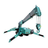
Maeda MC405C-3 Operation Manual (348 pages)
Mini-Crawler Crane
Brand:
Maeda
| Category:
Construction Equipment
| Size: 12 MB
Table of Contents
Table of Contents
3
Introduction
15
Safety Definitions
18
Safety Precautions
18
Safety Label Locations
25
Machine Body
25
Remote Control System
40
Electric Motor (Option)
42
850Kg Searcher Hook (Option)
43
Fly-Jib (Option)
46
Specifications, Terminology and Capacity Charts
49
Machine Features
50
Crane
50
Main Features
50
Safety Devices
50
Travelling Dolly
50
Crane Terminology
51
Terms and Definitions
51
Principle Specifications List
52
Standard and Electric Motor Option Specifications
52
Remote Control System Specifications
54
850 Kg Searcher Hook Specifications
55
Fly-Jib Specifications
56
Dimensional Drawings
57
Machine Dimensional Drawing
57
850 Kg Searcher Hook Dimensonal Drawing
58
Fly-Jib Dimensonal Drawing
59
Outrigger Width Dimensional Drawing
60
Rated Total Load Charts
61
Programmable Moment Limiter
61
Reading the Angle Indicator
61
Boom Length
62
Rated Total Load Chart for Standard Specification
64
Rated Total Load Chart - 4 Falls
65
Rated Total Load Chart - 2 Falls
66
Rated Total Load Chart - Single Fall
67
Rated Total Load Chart for 850 Kg Searcher Hook
68
Rated Total Load Chart for Fly-Jib
70
Working Radius/Lifting Height
71
Standard
71
During Pick & Carry
73
Working Radius/Lifting Height for 850 Kg Searcher Hook
74
Working Radius/Lifting Height for Fly-Jib
76
Machine Components
78
Travel and Crane Controls
80
Control Location
80
Acceleration Pedal
81
Boom Derricking Lever
81
Boom Telescoping Lever
81
Slewing Lever
81
Winch Lever
81
Left/Right Travelling Lever
82
Level Gauge
82
Outrigger Un-Set Warning Lamp (Yellow)
82
Travelling Lock Lever
82
Instrument Panel Sections
83
Switches
84
Monitors
87
Operation Seat
89
Reclining Adjustment
89
Seat Forward/Backward Slide Adjustment
89
Operation Related Precautions
90
Before Starting Engine
90
After Starting Engine
91
Cold Weather Operation
92
Cautions When Snow Covered or Frozen
92
Cautions under Cold Weather
93
Starting Engine
94
Checking after Starting Engine
94
Checking before Operation
94
Checking before Starting Engine
94
Normal Engine Start
94
Visible Checks
94
Starting Engine in Cold Weather
95
Operations and Checks after Starting Engine
96
Stopping Engine
98
Inspection after Stopping Engine
98
Travelling Position
99
Travelling Controls and Operation
99
Allowable Water Depth
99
Cautions When Travelling
99
Cautions on Upward/Downward Slope
100
Starting Travelling Machine
101
Preparation before Starting Travelling
101
Travelling Backward
101
Travelling Forward
101
Changing Machine Travelling Mode
102
Changing Travelling Speed Mode
102
Directional Controls
102
Changing the Machine Direction While Being Stopped
102
Changing Path While Travelling Forward/Backward
103
Spin Turns
103
Stopping/Parking Machine
104
Description on Outrigger and Crane Safety Devices
105
Functions of Outrigger Safety Devices
105
Outrigger Safety Devices
105
Check before Setting Outriggers
106
Outrigger Setting Operation
106
Crane Operations
107
Crane Stowing Operation
107
Machine Travelling Operation
108
Outrigger Stowing Operation
108
Check before Setting Outriggers
109
Description of Pick & Carry Safety Devices
109
Outrigger Setting Operation
109
Crane Operations
110
Pick & Carry Operation
110
Crane Stowing Operation
111
Outrigger Setting Operation
111
Outrigger Stowing Operation
111
Machine Travelling Operation
112
Outrigger Components
113
Outrigger Display
114
Outrigger Un-Set Warning Lamp (Yellow)
115
Outrigger Operation Panel
116
Work Selector Switch (Travel, Outrigger, Crane)
116
Outrigger Extension Switch
117
Outrigger Grounding Switches
117
Outrigger Setting
118
Outrigger Setting Precautions
118
Tasks to be Performed Upon Engine Stop
120
Tasks to be Performed after Starting Engine
122
Outrigger Extension Modes
124
Outrigger Maximum Extension
124
Outrigger Medium Extension
124
Outrigger Minimum Extension
125
Outrigger Stowing
125
Tasks to be Performed after Starting Engine
126
Tasks to be Performed Upon Engine Stop
128
Working with Crane
129
Crane Operation
136
Dos and Don'ts During Crane Operations
136
Before Crane Operations
138
Crane Operation Posture
139
Hook Raising/Lowering Operation
139
Boom Derricking Operation
140
Boom Telescoping Operation
140
Acceleration Operation
141
Slewing Operation
141
Crane Stowing Operation
142
Moment Limiter (Overload Detector)
144
Moment Limiter Features
144
Display of Moment Limiter Error Messages
145
Function of Moment Limiter
145
Mechanism of Moment Limiter
145
Moment Limiter Operations
146
Prohibited Actions after Auto Stop
146
Recovery Operation after Auto Stop
146
Moment Limiter Display
148
Boom Angle Upper Limit Switch and LED (Orange)
149
Descriptions of Switches on Moment Limiter Display
149
Wire Falls Selector Switch and Wire Falls Display LED (Blue)
149
Boom Angle Lower Limit Switch and LED (Orange)
150
Working Radius Upper Limit Switch and LED (Orange)
150
Cancel Switch
151
Check Switch
151
Lifting Height Upper Limit Switch and LED (Orange)
151
Actual Load Display Section
152
Descriptions of Moment Limiter Display
152
Rated Total Load Display Section
152
Boom Angle Display Section
153
Boom Length Display Section
153
Lifting Height Display Section
153
Outrigger Extension LED (Blue)
153
Over Winding LED (Red)
153
Working Radius Display Section
153
Load Factor Display (Yellow)
154
Load Factor LED (Changes to Green/Yellow/Red)
154
Moment Limiter Functions
155
Overload Warning
155
Working Envelope Restriction Warning
155
Over Winding Detector
156
Boom Lower Limit Detection
157
Boom Upper Limit Detection
157
Moment Limiter Starting Status
157
Number of Wires Selector Switch
157
Outrigger Extension Detection
157
Cancelling Working Envelope Setting
158
Moment Limiter Working Envelope Setting
158
Setting Working Envelope
158
Moment Limiter Override Switch
159
Cautions During Pick & Carry Operation
160
Cautions on Operations
160
Cautions on Worksite
160
Pick & Carry Operation
160
Rated Total Load and Working Range Caution During Pick & Carry
160
Pick & Carry Posture
161
Cancelling Pick & Carry Operation Posture
162
Pick & Carry Operations
162
Remote Control System Introduction
163
General
163
Precautions for Crane Operation - after Starting Engine
165
Precautions for Crane Operation - before Starting Engine
165
Precautions for Crane Operation - Terminating the Operation
166
Remote Control System Features
166
Functions of Remote Control System
167
Receiver
167
Transmitter
167
Remote Control System Components
168
Transmitter
168
Receiver Components
173
Fuse in the Receiver
174
Removal of the Fuse
174
Insertion of a Fuse
175
Mode Setting of the Transmitter
176
A Mode
176
Messages in the a Mode Screen
176
Opening a Mode Screen
176
An Example for Setting in the a Mode
179
Call out Crane Mode
180
Procedure in the Operation Mode
180
Call out Outrigger Mode
181
Remote Control System Verifications
182
Checking before Starting Engine
182
Checking before Turning on the Transmitter
182
Checking after Turning on the Transmitter
183
Checking Receiver
186
Checking after Starting Engine
187
Verification for the Engine Start and Stop
187
Checking "Outrigger Mode" Operation
188
Checking "Crane Mode" Operation
190
Remote Control Operation
192
Cautions before Operation
192
Operation in Outrigger Mode
192
Outrigger Setting
194
Outrigger Stowage
195
Operation in Crane Mode
196
Slewing Operation
197
Boom Derricking Operation
198
Boom Telescoping
198
Hook Raising and Lowering Operation
198
Automatic Hook Stow Function
199
Set-Up/Cancel Micro Speed and Enhanced Speed Mode
200
Engine Start and Reset Procedure
202
Engine Stop and Emergency Stop Procedure
202
Checking after Crane Operation
203
Electric Motor (Option)
204
Engine and Electric Motor Switch
205
Instrument Panel Sections
205
Power Supply Box
206
Power Unit
206
Inverter Unit
207
Main Breaker (with a Leak Detector)
207
DC12V Power Switch
208
AC Circuit Power Switch
209
Power Lamp (White)
209
Trouble Lamp (Red)
209
Electric Motor Operation
210
Checking after Starting Electric Motor
210
Checking before Starting Electric Motor
210
Connecting Power Supply Cable
210
Pre-Start Inspection
210
Pre-Start Visible Checks
210
Operation and Checking after Power Connection
212
Machine Operation
213
Disconnecting Power Supply Cable
214
Machine Stop and Checks after Stopping Machine
214
Searcher Hook Safety Precautions
215
Handling Precautions
215
Operating Precautions
215
Kg SEARCHER HOOK COMPONENTS (OPTION)
216
850 Kg SEARCHER HOOK MOMENT LIMITER DISPLAY
217
Cancel Switch
218
Searcher Hook Operation
220
Fly-Jib Safety Precautions
224
Fly-Jib Components (Option)
225
Fly-Jib Installation and Stowage
226
Fly-Jib Installation
226
Fly-Jib Stowage (Single Fall Hook Mode)
232
Change to Single Fall Hook from Main-Boom Hook Block
236
Removal of Fly-Jib Assembly
238
Installation of Fly-Jib Assembly
239
Fly-Jib Moment Limiter Control
243
Moment Limiter Display
243
Items of Moment Limiter Restriction for Operation
244
Operation Control by Moment Limiter
244
Restriction in Fly-Jib Mode
244
Instruction for Fly-Jib Operation
246
Moment Limiter Mode Change
246
Restriction for Boom Stowing Operation
246
Operation for Boom Retraction
248
Transportation
248
Transport Precautions
248
Loading/Unloading
250
Hoisting Machine
251
Cautions During Transportation
252
Cautions on Loading Machine
252
Maintenance and Inspection
253
General Maintenance Information and Precautions
254
Precautions before Maintenance
254
Precautions During Maintenance
256
Attach a Warning Tag
260
Cautions for Lubrication
260
Check Drain Oil and Oil Filter
260
Check the Service Meters
260
Handle Water and Oil at Adequate Temperature
260
Keep the Machine Clean
260
Protect Oil from Impurities
260
Use Clean Oil and Grease
260
Use Genuine Parts for Replacement
260
Use Pure Grease
260
Assure Safe Rubber Track
261
Cautions for Working in a Dusty Site
261
Do Not MIX Oil
261
Pre- and Post-Work Inspection
261
Basic Maintenance
261
Oil Handling
261
Coolant Handling
262
Filter Handling
262
Fuel Handling
262
Grease Handling
262
Stocking and Storage of Oil and Fuel
262
Electrical Part Handling
263
Hydraulic Equipment Handling
263
Breaking-In Machine
264
Legal Inspection
264
Consumables
265
Lubricating Oil
266
Special Tools and Standard Tightening Torque
267
Accessory Tools
267
Bolt and Nut Tightening Torque
267
Standard Tightening Torque List
267
Hose Connector Tightening Torque
269
Machinery Cover
270
Installing Machinery Cover
270
Removing Machinery Cover
270
Rear Cover
271
Installing Rear Cover
271
Removing Rear Cover
271
Fuses
272
Inspection
273
Pre-Start and Post-Start Inspection Items
273
Pre-Start Visible Checks
274
Crane
275
Hook Block
275
Outriggers
275
Wire Ropes
275
Check / Add Engine Coolant
276
Engine
276
Pre-Start Inspection - before Starting Engine
276
Tracks and Frame
276
Travel and Crane Controls
276
Check / Add Engine Oil
277
Check / Add Fuel
278
Check / Clean Water Separator
278
Check / Add Hydraulic Oil
279
Check / Add Slewing Motor Reduction Gear Case Oil
280
Check / Add Travelling Motor Reduction Gear Case Oil
280
Check Battery Charge Level
281
Check Dust Indicator
281
Check Fuse Box
282
Check Horn
282
Check Outrigger Display
282
Check Working Light Operation
282
Adjust Operation Seat
283
Check / Adjust Rubber Track Tension
283
Post-Start Inspection - after Starting Engine
283
Check Outrigger Safety Device Operation
285
Check Rubber Tracks for Damage and Wear
285
Check Outrigger Operation
287
Check Crane Operation
288
Check Moment Limiter Operation
289
Check over Winding Detector Operation
289
Check Engine Exhaust Gas Colour, Noise and Vibration
290
Check Outrigger Extension Positions
290
Periodic Maintenance Schedule
291
Periodic Maintenance
291
Periodic Maintenance Schedule
291
Periodic Maintenance Procedure
292
Tension
292
Grease Machine Units
293
Check Oil Level and Refill Oil in Winch Reduction Gear Case
295
Radiator and Oil Cooler Fin Inspection/Cleaning
296
Check / Adjust Belt Tension
296
Check / Refill Oil in Travelling Motor Reduction Gear Case
297
Replace Engine Oil and Oil Filter
298
Replace Fuel Filter Cartridge
299
Cartridge
299
Replace Hydraulic Oil Return Filter
300
Replace Hydraulic Oil Suction Filter
301
Slew Ring Mounting Bolt Inspection
302
Replace Air Cleaner Element
302
Replace Oil in Hydraulic Oil Tank
303
Replace Oil in Slewing Reduction Gear Case
304
Reduction Gearcase
304
Replace Oil in Winch Reduction Gear Case
305
Replace Oil in Winch Reduction Gearcase
305
Replace Oil in Travelling Motor Reduction Gearcase
306
Inspect / Adjust Inlet Valve and Exhaust Valve Clearance
307
Coolant
307
Inspect / Clean EGR Valve
308
Inspect/Adjust Inlet Valve and Exhaust Valve Clearance
307
Inspect / Clean / Test Fuel Injector
307
Check Crankcase Breather
307
Check / Replace Engine Coolant
307
General Machine Maintenance
308
Batteries
308
Battery Precautions
308
Cautions in Handling Battery
309
Cautions on Charging Battery
310
Installation
310
Remove / Install Battery
310
Starting Engine with Booster Cable
311
Rubber Tracks
313
General Information and Precautions
313
Inspection of Rubber Tracks
315
Replace Rubber Track
316
Wire Rope
317
General Information and Precautions
317
Inspecting Wire Rope
318
Winch Wire Rope - Correcting Twisted Rope
318
Winch Wire Rope - Removal
319
Winch Wire Rope - Installation
320
Checking / Adjusting Boom Telescoping Wire Rope
322
Inspection, Cleaning and Replacement of Air Cleaner
324
Inspection
324
Cleaning/Replacing the Element
325
Cleaning Inside Engine Cooling System
326
Cleaning Method
327
Draining Contaminant Water/Deposits in Fuel Tank
328
Draining Contaminant Water/Deposits in Water Separator
328
Long-Term Storage
330
Before Storing Machine
330
During Storage
330
After Storage
330
For Electric Motor
330
Cold Temperature Preparation
331
Lubrication
331
Coolant
331
Battery
331
Cautions after Completing the Operation
331
After the Cold Weather Is Gone
331
Kg SEARCHER HOOK INSPECTION and MAINTENANCE
332
Legal Inspection
332
Consumables
332
Inspection and Maintenance List
333
Pre-Start and Post-Start Inspection Items
333
Pre-Start - before Starting Engine
334
E-Boom, Frame and Hook
334
Greasing
334
Position Pin and Lynch Pin
334
Searcher Hook Fix Bolts
334
Pre-Start - after Starting Engine
334
Moment Limiter for Operation (Searcher Hook Mode)
334
Fly-Jib Inspection and Maintenance
335
Legal Inspection
335
Consumables
335
Inspection and Maintenance List
336
Pre-Start and Post-Start Inspection Items
336
Pre-Start - before Starting Engine
337
Boom and Frame
337
Electrical Wiring (Fuse Box)
337
Fly-Jib Fix Bolts
337
Pre-Start - after Starting Engine
337
Over Winding Detector
337
Greasing Fly-Jib Foot Pin
338
Moment Limiter for Operation (Fly-Jib Mode)
338
Winch and Boom
338
Irregular Maintenance
338
Replacement Winch Wire Rope
338
Greasing Machine Units
339
Troubleshooting
340
General
340
Machine Body
340
Engine
340
Electrical Components
341
Remote Control
342
Moment Limiter Error Causes and Actions to be Taken
345
Electric Motor
346
Advertisement
Maeda MC405C-3 Service Manual (358 pages)
Mini-Crawler Crane
Brand:
Maeda
| Category:
Construction Equipment
| Size: 25 MB
Table of Contents
Table of Contents
3
Item Page
4
General
9
Specification Dimensional Drawing
10
Dimensional Drawing of Outrigger Width
11
Principle Specification List
12
Standard Specification
12
Engines and Electric Moter Specification
13
Working Radius and Lifting Height
15
Working Radius and Lifting Height (Pick & Carry)
16
Total Rated Load Chart
17
Total Rated Load Chart at Wire Rope 4 Falls
17
Total Rated Load Chart at Wire Rope 2 Falls
18
Total Rated Load Chart at Wire Rope Single Fall
19
Crane Standard Pressure and Operating Timetable
20
Outrigger
20
Crane
20
Travelling Operation
20
Power Train Drawing
21
Construction & Maintenance
23
Hydraulic Circuit Diagram
23
Hydraulic Units Layout Diagram
27
Hydraulic Piping Diagram
30
CRANE ROTATING PARTS (Rotary Joint - Winch / Derricking / Telescopic Cylinder)
30
CRANE FIXED PARTS (Crane Control Valve - Rotary Joint / Slewing Motor)
32
TRAVEL LINE (Travel Control Valve - Terminal Assembly - Travel Motor)
36
Outrigger Lines
38
Outrigger Control Valve - or Select Valve - or / Slide Cylinder FR out (Front Right Side Out)
42
Outrigger Control Valve - or Select Valve - or / Slide Cylinder FR in (Front Right Side In)
43
Outrigger Control Valve - or Select Valve - or / Slide Cylinder FL out (Front Left Side Out)
44
Outrigger Control Valve - or Select Valve - or / Slide Cylinder FL in (Front Left Side In)
45
Outrigger Control Valve - or Select Valve - or / Slide Cylinder RR out (Rear Right Side Out)
46
Outrigger Control Valve - or Select Valve - or / Slide Cylinder RR in (Rear Right Side In)
47
Outrigger Control Valve - or Select Valve - or / Slide Cylinder RL out (Rear Left Side Out)
48
Outrigger Control Valve - or Select Valve - or / Slide Cylinder RL in (Rear Left Side In)
49
Pump Line
50
Hydraulic Oil Tank - Pump
52
Pump - Travel Control Valve
52
Tank / Drain Line
54
Crane Control Valve - Manifold Block - Oil Cooler - Tank (Return Filter)
56
OR Control Valve - Travel Control Valve - Manifold Block
56
Travel Motor - Terminal B - Hydraulic Oil Tank
57
Slewing Motor - Rotary Joint - Terminal B - Hydraulic Oil Tank
57
Merge Valve - Speed Increase Valve - Hydraulic Oil Tank
58
Pilot Line
60
Crane Control Valve - or Control Valve - Merge Valve
62
Travel Valve - Speed Increase Valve - Travel Motor
62
Electric Powered Line
64
Hydraulic Pump for Electric Operations - Hydraulic Pump for Engine / Hydraulic Oil Tank
65
Tank
66
Hydraulic Tank
66
Fuel Tank
68
Fuel Level Sensor
70
Return Mani-Block
71
Check Valve
71
Engine Assembly
74
ENGINE ASSEMBLY 3TNV88F-EPMB Yanmar
74
Engine Model
75
Name of each Section
76
Certification Name Plate
77
Emission Control Certification Name Plate
77
Diesel Fuel
78
Fuel System
78
Use of Adequate Fuels
78
Diesel Fuel Specifications
79
Bio-Diesel Fuels
79
Priming the Fuel System
80
Coolant
82
Coolant System
82
Use of Adequate Coolant
82
Engine Coolant Specifications
82
Lubricating Oil
83
Lubricating System
83
Use of Adequate Lubricant
83
Engine Oil Specifications
84
Periodic Maintenance Schedule
85
Trouble Shooting
86
Fuel Piping
90
Hydraulic Pump
92
Hydraulic Pump for Engine
92
Appearance and Specifications
92
Hydraulic Pump for Electric Operations
93
Appearance and Specifications
93
Trouble Shooting
94
Travel Control Valve
96
Exterior View and Specifications
96
Inner Parts
97
Inspection and Adjustment
98
Trouble Shooting
99
Traveling Motor
100
Exterior View and Specifications
100
Inner Parts
101
Outline
101
Basics of Functionality
102
Function of Automatic Control Valve
104
Function of Counter Balance Valve
106
Function of Parking Brake
107
Precautions for Use
108
Installation
108
Piping
108
Lubricating Oil for Gears
109
General Precautions
109
Crane Control Valve
110
Exterior View and Specifications
110
Hydraulic Circuit Diagram
111
Rgb Block
112
Accelerator Block
114
Function Block (Derrick, Winch, Telescopic, Slewing)
114
Solenoid Valve Functioning Principle
115
Outrigger Control Valve
118
Exterior View and Specifications
118
Inner Parts
120
Outrigger Select Valve
122
Exterior View and Specifications
122
Inner Parts
123
Crane Circuit Confluence Valve
124
EXTERIOR VIEW and SPECIFICATIONS
124
Inner Parts
125
Inspection and Adjustment
126
Trouble Shooting
126
Traveling Speed Select Valve
128
Exterior View and Specifications
128
Inspection and Adjustment
129
Trouble Shooting
129
Rotary Joint
130
Exterior View and Specifications
130
Inner Parts
131
Hook Block
132
Hook Block Inspection
134
Boom
136
Telescopic and Derrick Cylinder
140
Telescopic Cylinder
140
Telescopic Cylinder Hydraulic Circuit System
142
Counter Balance Valve (for Telescopic and Derrick Cylinder)
143
Structure
143
Trouble Shooting
143
Function
144
Sequence Valve (for Telescopic Cylinder)
145
Function
145
Mechanical Check Valve (for Telescopic Cylinder)
146
Left Side Derrick Cylinder
148
Right Side Derrick Cylinder
150
Winch
152
Winch Exterior View
152
Winch Unit Exterior View
154
Outline of Winch Unit
155
Hydraulic Oil Motor
156
Inner Parts
156
Operational Test
157
Basics of Functionality
157
Trouble Shooting
158
Winch Reduction Gear
160
Oil Replacement in Winch Reduction Gear Case
161
Replacement Winch Wire Rope
164
Slewing System
166
Exterior View
166
Slewing Bearing Wobble Limit Tolerance
167
Slewing Reduction Gear
168
Hydraulic Oil Motor Inner Parts
169
Slewing Motor Trouble Shooting
170
Outrigger
172
Front Outrigger
172
Rear Outrigger
174
Outrigger Cylinder
176
Outrigger Slide Cylinder
176
Single Check Valve (for Outrigger Slide Cylinder)
178
Front Outrigger Cylinder
180
Rear Outrigger Cylinder
182
Double Check Valve (for Outrigger Cylinder)
184
Assembly and Disassembly of Boom
186
Electric Circuit Diagram
193
Electrical Wiring System Diagram
195
Electric System
198
Engine Harness
198
Remote Controller, Valve, Electric Harness
202
Moment Limiter Harness
204
Electric Harness
206
Over-Winding Detector
208
Operation Principle
210
Tip-Over Warning Device
212
Moment Limiter
215
Moment Limiter Related
216
Display Unit and Converter
216
Front Outrigger Extension Detector
218
Rear Outrigger Extension Detector
220
Boom Displacement Detector
222
Angle Sensor
224
Length Sensor Code Reel
226
Load Detector
228
Pressure Sensors
229
Moment Limiter Accessory
230
Over Un-Winding Detector
232
Pick and Carry Related
234
Outrigger Safety Device
236
Rotary Position Detector
236
Ground Setting Detector
238
Boom Stowing Position Detector
240
Moment Limiter Overview and Features
242
External View of Moment Limiter
244
Display Unit
244
Converter
245
Block Diagram
246
Connector Diagram
247
Connector Pin Assignment
248
Converter Connectors
248
Display Unit Connectors (M2)
249
Input/Output
250
Converter
250
Display Unit
251
Display Unit Input
251
Display Unit Output
252
Displays
254
Switches
256
Display Unit; Detail of each Segment
258
Start-Up Sequence
260
Moment Limiter Functions
260
Display of Specific Indicators
261
Operation Range Limitation Control
261
Calibration Procedure
262
List of Items
262
Procedure
263
Calibration Work Flow
263
Call out of Calibration Mode
263
Calibration of Boom Length
264
Calibration of Boom Angle
266
Calibration of Weighing
268
Display Details at Calibration Mode
271
Test Mode
272
Call out of Test Mode
272
L01 (Rom/Ram Test)
273
L02 (Led Test)
273
L03 (Switch Test)
274
L04 Input Signal Test
275
L05 Output Signal Test
276
L06 (Load Factor Test)
277
L07 (Verification of Input from Converter)
277
L08 (Time Setting)
278
L09 (Display of the Time to Replace Butteries)
279
Pc Mode
280
Moment Limiter Operation Log Picking up Procedure
280
Moment Limiter Operation Log Deleting Procedure
285
Read Moment Limiter History
287
Error Messages
288
Trouble Shooting
290
Points for Input Voltage Measurement of each Sensor
292
Interactive Remote Control
294
Initial Mode Setting Procedure
294
Button Arrangement on Control Panel
294
Establishing Initial Mode
295
Initial Mode for User (a Mode)
296
Initial Mode for Service (B Mode)
299
Initial Mode for Maker (C Mode)
302
Initial Mode Setting
308
Receiver
310
Status Display
310
Control Print Card Lacations
312
Main Print Card (Upper Side) (Mc9141-A)
312
Main Print Card Lcd Display (Upper Side) (Mc9141-A)
313
Sub Print Card (Lower Side) (Mc9143-A)
314
Sub Print Card Lcd Display (Lower Side) (Mc9143-A)
315
Connector Pin Assignment
316
Valve Neutral Setting Procedure
318
Monitor Display Message
320
Normal Operation Message
320
Fuse in the Receiver
321
Voice Messages
323
Troubleshooting
324
Electric Motor
328
Electric Motor
329
Inverter Panel
329
Structural Drawing
330
External Appearance and Name of each Section
332
Name and Content of the Digital Operator
333
Detail of Inverter Set Items
335
Alarm Display and Countermeasure
336
Alarm Display
336
Fault Monitor Display
336
Method for Releasing (Resetting) the Trip Status
337
List of Alarm Codes
338
Troubleshooting
342
Inspection and Maintenance
348
Regular Inspection
348
Periodical Inspection
349
Disposal of the Inverter
351
Power Supply Box
352
Electric Circuit Diagram
354
Advertisement
Related Products
Maeda MC-405C
Maeda MC-174CRM
Maeda MC-305C-2
Maeda MC815C
Maeda MC285C-3
Maeda MC285CB-3
Maeda MC305C-3
Maeda HIRD MC815
Maeda MC174
Maeda MC285C-2
Maeda Categories
Construction Equipment
More Maeda Manuals
Login
Sign In
OR
Sign in with Facebook
Sign in with Google
Upload manual
Upload from disk
Upload from URL