Sign In
Upload
Manuals
Brands
Madison Manuals
Measuring Instruments
MD4814-X2
Madison MD4814-X2 Manuals
Manuals and User Guides for Madison MD4814-X2. We have
2
Madison MD4814-X2 manuals available for free PDF download: Instruction Manual
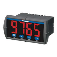
Madison MD4814-X2 Instruction Manual (46 pages)
Process & Temperature Meters
Brand:
Madison
| Category:
Measuring Instruments
| Size: 3 MB
Table of Contents
Table of Contents
3
Introduction
6
Ordering Information
6
Accessories
7
Specifications
8
General
8
Process Input
8
Temperature Inputs
8
Relays Option
9
Serial Communications
9
Isolated 4-20 Ma Transmitter Output
9
External Button Contacts (X2 Models Only)
9
Compliance Information
10
Safety
10
Electromagnetic Compatibility
10
EU Declaration of Conformity
10
Safety Information
10
Installation
11
Unpacking
11
Panel Mounting
11
Mounting Dimensions
11
Figure 1. Panel Cutout and Mounting
11
Figure 2. Meter Dimensions - Side View
11
Figure 3. Case Dimensions - Top View
11
Connections
12
Connector Labeling
12
Power Connections
12
Figure 4. Connector Labeling for MD4814-110-00
12
Figure 5. Connector Labeling for MD4814-110-02
12
Figure 6. Connector Labeling for MD4814-012-00-4
12
Figure 7. Connector Labeling for MD4814-110-X2
12
Figure 8. Power Connections
12
Signal Connections
13
Figure 9. Transmitter Powered by Internal Supply (Optional)
13
Figure 10. Transmitter Powered by External Supply or Self-Powered
13
Figure 11. Voltage Input Connections
13
Figure 12. Thermocouple Input Connections
13
Figure 13. Three-Wire RTD Input Connections
13
Figure 14. Two-Wire RTD Input Connections
13
Serial Communication
14
Relays and 24 V Output Connections
14
Switching Inductive Loads
14
Figure 15. Four-Wire RTD Input Connections
14
Figure 16. Relay & 24 V Output Connections
14
Figure 17. AC and DC Loads Protection
14
Figure 18. Low Voltage DC Loads Protection
14
Ma Output & Input Signal Connections
15
External Button Contacts on MD4814-X2
15
Figure 19. 4-20 Ma Output Powered Externally
15
Setup and Programming
16
Overview
16
Front Panel Buttons and Status LED Indicators
16
Display Functions and Messages
17
Main Menu
18
Setting Numeric Values
18
Setting up the Meter (Setu)
18
Setting the Input Signal (Inpt)
18
Setting the Decimal Point (DC. P T)
19
Setting the Temperature Scale (F C)
19
Programming the Meter (Prog)
19
Scaling the Meter (Scal)
19
Calibrating the Meter (Cal)
20
Recalibrating Temperature Inputs (Cal)
20
Recalibrating Process Inputs (Ical)
20
Setting the Relay Operation (Rely)
21
Relay and Alarm Operation
22
Scaling the 4-20 Ma Analog Output (Aout)
27
Program the Sensor Break Output Value (Sebr)
27
Analog Output When Display Is out of Range
27
Setting up the Password (Pass)
28
Locking the Meter
28
Unlocking the Meter
28
Advanced Features Menu
28
Advanced Features Menu & Display Messages
28
Offset Adjustment (Adj)
29
Noise Filter (Fltr)
29
Noise Filter Bypass (Byps)
29
Serial Communications (Serl)
30
Protocol Selection Menu (Prot)
30
Select Menu (Selc)
30
Linear or Square Root Function (Linr or Sqrt)
30
Low-Flow Cutoff (Cutf)
30
Display Intensity (Inty)
31
Meter Copy Function (Copy)
31
Figure 20. Meter Copy Connection
31
Meterview Software
32
Remote Programming
32
Data Acquisition
32
Monitoring
32
Monitoring System Parts
33
Meterview Installation
33
Running Meterview the First Time
33
Enable Meter and Select Meter Address
33
Meterview Main Window
33
Main Window Menus
34
Configuration Window
35
File Menu
35
Tools Menu
35
Password Menu
35
Input Tab
36
Set up Input Type
36
Set up Decimal Point
36
Set up Temperature Unit
36
Set up Temperature Sensor
36
Scaling Tab
37
Relays/Alarms Tab
37
Advanced Tab
37
Info Tab
37
Customize Window
37
Serial Communication Setup
38
Relays/Alarms Status
38
Logging Meter Data to File
38
Log File Sample
38
Internal Calibration (Ical)
39
Operation
40
Front Panel Buttons Operation
40
Maximum/Minimum Readings
40
Troubleshooting
41
Diagnostics Menu (Diag)
41
Determining Software Version
41
Reset Meter to Factory Defaults
41
Factory Defaults & User Settings
42
Troubleshooting Tips
43
Quick Interface Reference Guide
44
Advertisement
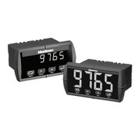
Madison MD4814-X2 Instruction Manual (72 pages)
Process Meters
Brand:
Madison
| Category:
Measuring Instruments
| Size: 1 MB
Table of Contents
Introduction
2
Ordering Information
3
Table of Contents
4
Specifications
7
General
7
Process Input
8
Temperature Inputs
9
Relays Option
10
Isolated 4-20 Ma Transmitter Output
11
Serial Communications
11
Compliance Information
12
Safety
12
Electromagnetic Compatibility
12
Safety Information
13
Installation
14
Unpacking
14
Panel Mounting
14
Figure 1. Panel Cutout and Mounting
14
Connections
15
Connector Labeling
15
Figure 2. Labeling for 2 Relay, Analog Out, & 24 V Supply Model
15
Power Connections
16
Signal Connections
16
Figure 3. Power Connections
16
Figure 4. Transmitter Powered by Ext. Supply or Self-Powered
16
Figure 5. Transmitters Powered by Internal Supply (Optional)
17
Figure 6. Voltage Input Connections
17
Figure 7. Thermocouple Input Connections
18
Figure 8. Three-Wire RTD Input Connections
18
Figure 9. Two-Wire RTD Input Connections
19
Figure 10. Four-Wire RTD Input Connections
19
Serial Communication
20
Relays and 24 V Output Connections
20
Switching Inductive Loads
20
Figure 11. Relay & 24 V Output Connections
20
Figure 12. AC and DC Loads Protection
20
Figure 13. Low Voltage DC Loads Protection
21
4-20 Ma Output & Input Signal Connections
22
Figure 14. 4-20 Ma Output & Input Signal Powered by Meter
22
Figure 15. 4-20 Ma Output Powered Externally
22
Setup and Programming
23
Front Panel Buttons and Status LED Indicators
24
Display Functions and Messages
25
Main Menu
28
Setting Numeric Values
28
Setting up the Meter (Setu)
29
Setting the Input Signal (Inpt)
30
Setting the Decimal Point (DC. P T)
31
Setting the Temperature Scale (F C)
31
Programming the Meter (Prog)
32
Scaling the Meter (Scal)
33
Calibrating the Meter (Cal)
35
Recalibrating Temperature Inputs (Cal)
35
Recalibrating Process Inputs (Ical)
36
Setting the Relay Operation (Rely)
37
Relay and Alarm Operation
41
Pump Alternation Control Operation
46
Scaling the 4-20 Ma Analog Output (Aout)
47
Program the Sensor Break Output Value (Sebr)
48
Analog Output When Display Is out of Range
48
Setting up the Password (Pass)
49
Locking the Meter
49
Unlocking the Meter
49
Advanced Features Menu
50
Advanced Features Menu & Display Messages
51
Offset Adjustment (Adj)
53
Noise Filter (Fltr)
53
Noise Filter Bypass (Byps)
54
Serial Communications (Serl)
54
Protocol Selection Menu (Prot)
54
Select Menu (Selc)
55
Linear or Square Root Function (Linr or Sqrt)
55
Low-Flow Cutoff (Cutf)
56
Display Intensity (Inty)
56
Meter Copy Function (Copy)
57
Figure 16. Meter Copy Connection
57
Internal Calibration (Ical)
59
Operation
62
Front Panel Buttons Operation
62
Maximum/Minimum Readings
63
Mounting Dimensions
64
Figure 17. Meter Dimensions - Side View
64
Figure 18. Case Dimensions - Top View
64
Troubleshooting
65
Diagnostics Menu (Diag)
65
Determining Software Version
65
Reset Meter to Factory Defaults
66
Factory Defaults & User Settings
67
Troubleshooting Tips
69
Quick Interface Reference Guide
70
Advertisement
Related Products
Madison MD4814
Madison MD4815
Madison MAD-LPRETRO
Madison MAD-HIGHPOWER400CD
madison MAD-RT500-WD
Madison MAD1305 Series
Madison MEK 61128
Madison MAD-LINK
Madison MAD-RT200SP
Madison MAD-HNB100
Madison Categories
Speakers
Turntable
Amplifier
Radio
Accessories
More Madison Manuals
Login
Sign In
OR
Sign in with Facebook
Sign in with Google
Upload manual
Upload from disk
Upload from URL