Table of Contents
Advertisement
Quick Links
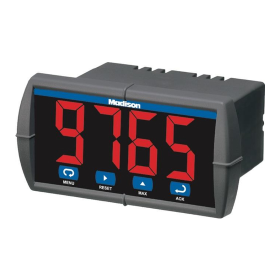
MD4814 & MD4814-X2 Process & Temperature Meters
Instruction Manual
•
1/8 DIN Digital Panel Meter with NEMA 4X, IP65 Front
•
4-20 mA, ± 10 V, TC & RTD Field Selectable Inputs
•
Easy Field Scaling in Engineering Units without Applying an Input
•
Full 4-Digit Display, 0.56" (14.2 mm) or 1.20" (30.5 mm)
•
Shallow Depth Case Extends Only 3.6" (91 mm) Behind Panel
•
Isolated 24 VDC @ 200 mA Transmitter Power Supply Option
•
2 Relays + Isolated 4-20 mA Output Options
•
Free PC-Based MeterView Programming & Monitoring Software
•
No Assembly Required
•
Sunlight Readable Display
•
Operating Temperature Range: -40 to 65°C (-40 to 149°F)
•
UL & C-UL Listed. E160849; UL 508 Industrial Control Equipment
•
Input Power Options: 85-265 VAC / 90-265 VDC or 12-36 VDC / 12-24 VAC
•
Duplex Pump Controller with Alternation Capability
•
External Contacts for Remote Button Operation (MD4814-X2 Only)
•
USB, RS-232, & RS-485 Serial Communication Adapters Options
•
Modbus RTU Communication Protocol Standard
•
Copy Meter Settings to Other MD4814 Meters
•
Password Protection
•
Max/Min Display
•
High & Low Alarms with Multiple Reset Actions
•
Stainless Steel Sun Hood Accessory Available
•
3-Year Warranty
Madison Company
27 Business Park Dr • Branford CT 06405 USA
Tel (203) 488-4477
www.madisonco.com
Advertisement
Table of Contents
Troubleshooting

Related Manuals for Madison MD4814-X2


Summary of Contents for Madison MD4814-X2
- Page 1 Input Power Options: 85-265 VAC / 90-265 VDC or 12-36 VDC / 12-24 VAC • Duplex Pump Controller with Alternation Capability • External Contacts for Remote Button Operation (MD4814-X2 Only) • USB, RS-232, & RS-485 Serial Communication Adapters Options •...
- Page 2 MD4814 & MD4814-X2 Process & Temperature Meters Instruction Manual Disclaimer FREE MeterView The information contained in this document is Programming Software subject to change without notice. Madison Company makes no representations or warranties with respect to the contents hereof and specifically disclaims any implied warranties of merchantability or fitness for a particular purpose.
-
Page 3: Table Of Contents
MD4814 & MD4814-X2 Process & Temperature Meters Instruction Manual Table of Contents Introduction ......................6 Ordering Information ..................6 Accessories ......................7 Specifications ..................... 8 General ......................8 Process Input ....................8 Temperature Inputs ..................8 Relays Option ....................9 Serial Communications .................. - Page 4 MD4814 & MD4814-X2 Process & Temperature Meters Instruction Manual Advanced Features Menu ................28 Advanced Features Menu & Display Messages .......... 28 Offset Adjustment (Adj) ................29 Noise Filter (fltr) ..................29 Noise Filter Bypass (byps) ................29 Serial Communications (serl) ..............30 Protocol Selection Menu (Prot) ..............
- Page 5 MD4814 & MD4814-X2 Process & Temperature Meters Instruction Manual Table of Figures Figure 1. Panel Cutout and Mounting ..............11 Figure 2. Meter Dimensions – Side View ............11 Figure 3. Case Dimensions – Top View .............. 11 Figure 4. Connector Labeling for MD4814-110-00 ..........12 Figure 5.
-
Page 6: Introduction
PDA8006 USB Serial Adapter for Programming height is an astounding 1.2" (30.5 mm). The Meter with MeterView Software MD4814-X2 can be read easily from distances of up to PDA8485-I USB to RS-485 isolated converter 30 feet! The intensity of the display on both versions of the MD4814 can be adjusted to compensate for various lighting conditions, especially direct sunlight. -
Page 7: Accessories
MD4814 & MD4814-X2 Process & Temperature Meters Instruction Manual Accessories Plastic NEMA 4X Enclosure PDA18DINSH The PDA18DINSH Sun Hood improves the readability of 1/8 DIN digital panel meters when they are mounted in direct sunlight by shading the instrument from the sun. -
Page 8: Specifications
MD4814 & MD4814-X2 Process & Temperature Meters Instruction Manual Specifications Process Input Inputs 0-20 mA, 4-20 mA, 1-5 V, ±10 V Except where noted all specifications apply to Transmitter Isolated, one or two transmitter sup- operation at +25°C. Supply plies P1: 24 VDC ±10% @ 200 mA max (-10 option) P1 &... -
Page 9: Relays Option
MD4814 & MD4814-X2 Process & Temperature Meters Instruction Manual Relays Option Isolated 4-20 mA Transmitter Output Rating 2 Form C (SPDT); rated 3 A @ 30 VDC or 3 A @ 250 VAC resistive load; Scaling Range 1.00 to 23.00 mA; reverse scaling 1/14 HP (≈... -
Page 10: Compliance Information
MD4814 & MD4814-X2 Process & Temperature Meters Instruction Manual Compliance Information EU Declaration of Conformity Safety For shipments to the EU and UK, a Declaration of Ul Listed USA and Canada Conformity can be found at www.predig.com/docs. UL 508 Industrial Control Equipment... -
Page 11: Installation
MD4814 & MD4814-X2 Process & Temperature Meters Instruction Manual Installation Mounting Dimensions There is no need to remove the meter from its case to complete the installation, wiring, and setup of the meter. Unpacking Remove the meter from box. Inspect the packaging and contents for damage. -
Page 12: Connections
MD4814 & MD4814-X2 Process & Temperature Meters Instruction Manual Connections All connections are made to removable screw terminal connectors located at the rear of the meter. • Use copper wire with 60°C or 60/75°C insulation for all line voltage connections. Observe all safety regulations. -
Page 13: Signal Connections
MD4814 & MD4814-X2 Process & Temperature Meters Instruction Manual Signal Connections Thermocouple and RTD Connections Signal connections are made to a five-terminal connector labeled SIGNAL shown in Figures 4-21. See The following figures show examples for page 12. Connector Labeling. The COM (common) thermocouple and RTD connections. -
Page 14: Serial Communication
MD4814 & MD4814-X2 Process & Temperature Meters Instruction Manual Switching Inductive Loads The use of snubbers to suppress electrical noise is strongly recommended when switching inductive loads to prevent disrupting the microprocessor’s operation. The snubbers also prolong the life of the relay contacts. -
Page 15: Ma Output & Input Signal Connections
4-20 mA Output & Input Signal External Button Contacts on Connections MD4814-X2 The MD4814-X2, with an optional 4-20 mA output, The MD4814-X2 is equipped with four external button can be used as an isolated temperature transmitter contacts that can be used to remotely operate the with a big display by converting the thermocouple or MD4814-X2’s front panel buttons. -
Page 16: Setup And Programming
MD4814 & MD4814-X2 Process & Temperature Meters Instruction Manual Setup and Programming Front Panel Buttons and Status LED Indicators This section describes how to program the MD4814 meter using the front panel buttons. The MD4814 me- MD4814 Standard Display ter can also be programmed using Meterview Soft-... -
Page 17: Display Functions And Messages
MD4814 & MD4814-X2 Process & Temperature Meters Instruction Manual Display Functions and Messages Display Parameter Action/Setting Set1 Set 1 Program set point 1 The meter displays various functions and messages rSt1 Reset 1 Program reset point 1 during setup/programming and operation. The... -
Page 18: Main Menu
MD4814 & MD4814-X2 Process & Temperature Meters Instruction Manual Setting Up the Meter (setu) Main Menu The main menu consists of the most commonly used The Setup menu is used to select: functions: Setup and Password. Input signal the meter will accept •... -
Page 19: Setting The Decimal Point (Dc. P T)
MD4814 & MD4814-X2 Process & Temperature Meters Instruction Manual If RTD is selected, the display shows A385 or A392. Programming the Meter (prog) Select the coefficient to match the RTD sensor, either 0.00385 (A385, European curve) or 0.00392 (A392, The meter may either be scaled (ScAL) without American curve). -
Page 20: Calibrating The Meter (Cal)
MD4814 & MD4814-X2 Process & Temperature Meters Instruction Manual Minimum Input Span Recommended Calibration Points The minimum input span is the minimum difference To recalibrate the meter, it is recommended to use between input 1 and input 2 signals required to the Fahrenheit scale;... -
Page 21: Setting The Relay Operation (Rely)
MD4814 & MD4814-X2 Process & Temperature Meters Instruction Manual Setting the Relay Operation (rely) Setting the Relay Action The relays’ Action menu allows the user to set up the This menu allows you to set up the operation of the operation of the relays. -
Page 22: Relay And Alarm Operation
MD4814 & MD4814-X2 Process & Temperature Meters Instruction Manual Setting Fail-Safe Operation Sensor Break Operation The fail-safe operation is set independently for each The following graphs illustrate the operation of how relay. Select on to enable or select off to disable fail- the meter reacts when a sensor break is detected. - Page 23 MD4814 & MD4814-X2 Process & Temperature Meters Instruction Manual Low Alarm Operation (Set < Reset) Time Delay Operation The following graphs show the operation of the time delay function. If the signal crosses the set point, the On time delay timer starts and the relay trips when the time delay has elapsed.
- Page 24 MD4814 & MD4814-X2 Process & Temperature Meters Instruction Manual High Alarm with Fail-Safe Operation Low Alarm with Fail-Safe Operation (Set > Reset) (Set < Reset) Fail-safe operation: relay coil is energized in Fail-safe operation: relay coil is energized in non-alarm condition. In case of power failure, non-alarm condition.
- Page 25 MD4814 & MD4814-X2 Process & Temperature Meters Instruction Manual Pump Controller with Dual-Pump Alternation The MD4814 can be used as a low-cost pump controller when combined with a continuous level transmitter. One of the most common pump control application is shown below: controlling and alternating two pumps. The goal is to control the level between 1000 and 6000 gallons.
- Page 26 MD4814 & MD4814-X2 Process & Temperature Meters Instruction Manual...
-
Page 27: Scaling The 4-20 Ma Analog Output (Aout)
MD4814 & MD4814-X2 Process & Temperature Meters Instruction Manual Scaling the 4-20 mA Analog Output Program the Sensor Break Output (Aout) Value (SEbr) The 4-20 mA analog output can be scaled to provide The sensor break value corresponds to the output a 4-20 mA signal for any display range selected. -
Page 28: Setting Up The Password (Pass)
MD4814 & MD4814-X2 Process & Temperature Meters Instruction Manual Setting Up the Password (pass) Forgot the Password? The password may be disabled by the following The Password menu is used to program a four-digit procedure: password to prevent unauthorized changes to the Note display reading prior to pressing the Menu programmed parameter settings. -
Page 29: Offset Adjustment (Adj)
MD4814 & MD4814-X2 Process & Temperature Meters Instruction Manual Offset Adjustment (Adj) Display Functions and Messages This parameter allows the user to select an offset Display Parameter Action/Setting adjustment to the temperature being displayed. Offset done Done Copy function completed adjustment values can be either positive or negative and can be any number within 19.9. -
Page 30: Serial Communications (Serl)
MD4814 & MD4814-X2 Process & Temperature Meters Instruction Manual Serial Communications (serl) Linear or Square Root Function (linr or Sqrt) The meter is equipped with serial communications capability as a standard feature using PDC protocol Meters are set up at the factory for linear function. -
Page 31: Display Intensity (Inty)
MD4814 & MD4814-X2 Process & Temperature Meters Instruction Manual Display Intensity (inty) Meter Cloning Instructions The Display Intensity function allows the selection of eight levels of intensity for various lighting conditions. • Do not connect the two meters to the same 4-20 mA loop while cloning. -
Page 32: Meterview Software
MD4814 & MD4814-X2 Process & Temperature Meters Instruction Manual Meterview Software Remote Programming MeterView software allows all setup parameters to be programmed remotely from a PC and saved to a file for reporting or programming other meters. Data Acquisition MeterView software provides a convenient way to col- lect the data generated by the MD4814 serial output. -
Page 33: Monitoring System Parts
MD4814 & MD4814-X2 Process & Temperature Meters Instruction Manual Monitoring System Parts MeterView Main Window The following table illustrates the parts needed to The main MeterView window shows the present monitor 10 MD4814 meters: reading(s), relays/alarm status, tag number(s) and selected engineering units, along with other... -
Page 34: Main Window Menus
MD4814 & MD4814-X2 Process & Temperature Meters Instruction Manual Main Window Menus Right Click Menu By right clicking on a meter on the screen a menu will The MeterView main window contains the following appear with the following options: menus: •... -
Page 35: Configuration Window
MD4814 & MD4814-X2 Process & Temperature Meters Instruction Manual Configuration Window File Menu The following options are available from the File Click on Configure in the right click menu to open a menu: meter’s configuration window. The following settings 1. Save Configuration to save the present can be programmed from this window: settings to a file. -
Page 36: Input Tab
MD4814 & MD4814-X2 Process & Temperature Meters Instruction Manual Input Tab Set Up Temperature Unit In the configuration window, click on the Input tab to Click on the arrow next to the Degrees F box and then view the input options. -
Page 37: Scaling Tab
MD4814 & MD4814-X2 Process & Temperature Meters Instruction Manual Scaling Tab Info Tab In the configuration window, click on the Scaling tab In the configuration window, click on the info tab to to view the scaling settings for process inputs (current view the firmware number and version. -
Page 38: Serial Communication Setup
MD4814 & MD4814-X2 Process & Temperature Meters Instruction Manual Serial Communication Setup Logging Meter Data to File 1. Click on the arrow next to the Interval box to select an interval from 2 to 60 or select manual Addresses for MD4814 Meter... -
Page 39: Internal Calibration (Ical)
MD4814 & MD4814-X2 Process & Temperature Meters Instruction Manual Internal Calibration (ICal) For instructions on how to program numeric values see Setting Numeric Values, page 18. • There is no need to recalibrate the meter when first received from the factory. -
Page 40: Operation
MD4814 & MD4814-X2 Process & Temperature Meters Instruction Manual Operation Maximum/Minimum Readings The main function of the front panel buttons during For process inputs, the meter is capable of accepting operation is to display the maximum and minimum positive and negative signals and displaying these readings reached by the process or temperature signals in engineering units from -1999 to 9999 (e.g. -
Page 41: Troubleshooting
MD4814 & MD4814-X2 Process & Temperature Meters Instruction Manual Troubleshooting Reset Meter to Factory Defaults When the parameters have been changed in a way Due to the many features and functions of the meter, that is difficult to determine what’s happening, it might it’s possible that the setup of the meter does not... -
Page 42: Factory Defaults & User Settings
MD4814 & MD4814-X2 Process & Temperature Meters Instruction Manual Factory Defaults & User Settings Parameter Display Default User Setting Setting The following table shows the factory setting for most of the programmable parameters on the meter. Next Protocol to the factory setting, the user may record the new protocol setting for the particular application. -
Page 43: Troubleshooting Tips
MD4814 & MD4814-X2 Process & Temperature Meters Instruction Manual Troubleshooting Tips This meter is a highly sophisticated instrument with an extensive list of features and capabilities. If the front panel but- tons are used to program the meter, it may be a difficult task to keep everything straight. That is why we strongly rec- ommend the use of the MeterView software for all programming activities. -
Page 44: Quick Interface Reference Guide
MD4814 & MD4814-X2 Process & Temperature Meters Instruction Manual Quick Interface Reference Guide Run Mode A385 4-20 mA Input Display A392 Max/Min 0-10 V Setup Type J Type K Password Type T Type T.0 Locked Unlocked Type E TC or RTD? - Page 45 MD4814 & MD4814-X2 Process & Temperature Meters Instruction Manual Pushbutton Function Menu Go to Programming Mode or leave Programming, Advanced Features, and Max/Min Modes. Right Arrow Move to next digit. Up Arrow Move to next selection or increment digit. Enter/Ack Accept selection/value and move to next selection.
- Page 46 MD4814 & MD4814-X2 Process & Temperature Meters Instruction Manual Contact Madison Company Sales & Technical Support Call: (203) 488-4477 or (800) 466-5383 Fax: (203) 481-5036 Email: info@madisonco.com For the latest version of this manual please visit www.madisonco.com Madison Company 27 Business Park Dr • Branford CT 06405 USA Tel (203) 488-4477 www.madisonco.com...
Need help?
Do you have a question about the MD4814-X2 and is the answer not in the manual?
Questions and answers