Sign In
Upload
Manuals
Brands
Madison Manuals
Measuring Instruments
MD4815
Madison MD4815 Manuals
Manuals and User Guides for Madison MD4815. We have
1
Madison MD4815 manual available for free PDF download: Instruction Manual
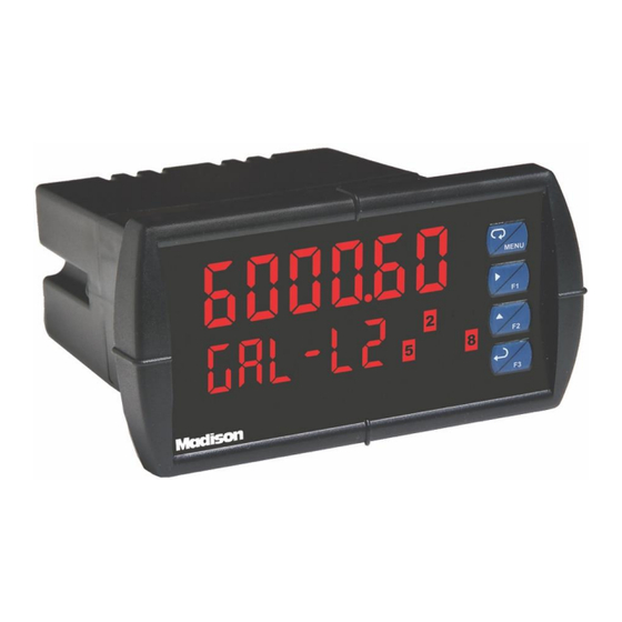
Madison MD4815 Instruction Manual (46 pages)
Analog Input Process Meter
Brand:
Madison
| Category:
Measuring Instruments
| Size: 3 MB
Table of Contents
Table of Contents
3
Introduction
6
Ordering Information
6
Accessories
7
Specifications
8
General
8
Process Input
9
Relays
9
Isolated 4-20 Ma Transmitter Output
10
USB Connection
10
On-Board Digital Input (F4)
10
Modbus ® RTU Serial Communications
10
Meterview Pro
10
Compliance Information
11
Safety
11
Electromagnetic Compatibility
11
EU Declaration of Conformity
11
Safety Information
11
Installation
11
Unpacking
11
Panel Mounting Instructions
12
Mounting Dimensions
12
Figure 1. 1/8 DIN Panel Cutout Dimensions
12
Figure 2. Panel Mounting Details
12
Figure 3. Meter Dimensions - Side View
12
Figure 4. Meter Dimensions - Top View
12
Installation Overview
13
Meterview Pro Software
13
Meterview Pro Installation
13
Transmitter Supply Voltage Selection (P+, P-)
14
Connections
14
Connectors Labeling
14
Figure 5. Transmitter Supply Voltage Selection
14
Figure 6. MD4815-###-#0 Connectors Label
14
Figure 7. MD4815-###-#2 Connectors Label
14
Figure 8. MD4815-###-#0-4 Connectors Label
14
Figure 9. MD4815-###-#4 Connectors Label
14
Figure 10. MD4815-###-#2-4 Connectors Label
14
Figure 11. MD4815-###-#4-4 Connectors Label
14
Power Connections
15
Signal Connections
15
Modbus RTU Serial Communications
15
Relay Connections
15
Figure 12. Power Connections
15
Figure 13. Transmitters Powered by Internal Supply
15
Figure 14. Transmitter Powered by External Supply or Self-Powered
15
Figure 15. Voltage Input Connections
15
Figure 16. Relay Connections
15
Switching Inductive Loads
16
F4 Digital Input Connections
16
4-20 Ma Output Connections
16
Analog Output Power Supply
16
Figure 17. AC and DC Loads Protection
16
Figure 18. Low Voltage DC Loads Protection
16
Figure 19. F4 Digital Input Connections
16
Figure 20. 4-20 Ma Output Connections
16
Figure 21. Analog Output Supply Powering Other Devices
16
External Relays & Digital I/O Connections
17
Interlock Relay Feature
17
Figure 22. Expansion Module & DIN Rail Mounting Kit
17
Figure 23. External Relays Module Connections
17
Figure 24. Digital I/O Module Connections
17
Figure 25. Interlock Connections
17
Setup and Programming
18
Overview
18
Front Panel Buttons and Status LED Indicators
18
Display Functions & Messages
19
Main Menu
20
Setting Numeric Values
21
Setting up the Meter (Setup)
21
Setting the Input Signal (Input)
21
Setting the Display Units or Custom Tags (Units)
22
Setting the Decimal Point (Dec Pt)
22
Programming the Meter (Prog)
23
Setting the Display Parameter & Intensity (Dsplay)
25
Display Intensity (D-Inty)
25
Setting the Relay Operation (Relay)
26
Setting the Relay Action
26
Programming Set and Reset Points
27
Setting Fail-Safe Operation
27
Programming Time Delay
27
Relay Action for Loss of 4-20 Ma Input (Loop Break)
27
Relay and Alarm Operation Diagrams
27
High Alarm Operation (Set > Reset)
27
Low Alarm Operation (Set < Reset)
28
High Alarm with Fail-Safe Operation (Set > Reset)
28
Low Alarm with Fail-Safe Operation (Set < Reset)
28
Time Delay Operation
28
Pump Alternation Control Operation
29
Relay Sampling Operation
29
Relay Operation Details
30
Overview
30
Relays Auto Initialization
30
Fail-Safe Operation
30
Front Panel Leds
30
Latching and Non-Latching Relay Operation
30
Non-Latching Relay (Auto)
31
Non-Latching Relay with Manual Reset (A-Nman)
31
Latching Relay (Latch)
31
Latching Relay with Clear (Lt-Clr)
31
Acknowledging Relays
32
Pump Alternation Control Applications (Altern)
32
Setting up the Interlock Relay (Force On) Feature
33
Scaling the 4-20 Ma Analog Output (Aout)
34
Reset Menu (Reset)
34
Manual Control Menu (Contrl)
34
Setting up the Password (Pass)
35
Protecting or Locking the Meter
35
Making Changes to a Password Protected Meter
35
Disabling Password Protection
35
Advanced Features Menu
36
Advanced Features Menu & Display Messages
36
Noise Filter (Filter)
37
Noise Filter Bypass (Bypass)
37
Rounding Feature (Round)
37
Modbus RTU Serial Communications (Serial)
37
Select Menu (Select)
38
Input Signal Conditioning (Functn)
38
Low-Flow Cutoff (Cutoff)
39
Analog Output Programming (Aoutpr)
39
Programmable Function Keys User Menu (User)
40
Tare (Tare)
40
Internal Source Calibration (ICAL)
41
Meter Operation
42
Front Panel Buttons Operation
42
Function Keys Operation
42
F4 Operation
42
Maximum/Minimum Readings
42
Troubleshooting
43
Diagnostics Menu (Diag)
43
Determining Software Version
43
Reset Meter to Factory Defaults
43
Factory Defaults & User Settings
44
Troubleshooting Tips
45
Advertisement
Advertisement
Related Products
Madison MD4814
Madison MD4814-X2
Madison MAD-TA15BT
madison MAD-RT300SP
Madison MAD-HIGHPOWER400
Madison MAD-MELODY
Madison MAD-CD10
Madison MAD1305BK
Madison MAD-TA80BT
Madison MAD-VR60
Madison Categories
Speakers
Turntable
Amplifier
Radio
Accessories
More Madison Manuals
Login
Sign In
OR
Sign in with Facebook
Sign in with Google
Upload manual
Upload from disk
Upload from URL