Sign In
Upload
Manuals
Brands
Lumenis Manuals
Medical Equipment
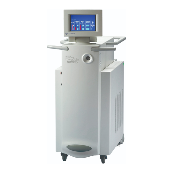
VersaPulse PowerSuite
Lumenis VersaPulse PowerSuite Manuals
Manuals and User Guides for Lumenis VersaPulse PowerSuite. We have
1
Lumenis VersaPulse PowerSuite manual available for free PDF download: Service Manual
Lumenis VersaPulse PowerSuite Service Manual (179 pages)
Brand:
Lumenis
| Category:
Medical Equipment
| Size: 1 MB
Table of Contents
Table of Contents
5
General Information
5
Installation
5
Theory of Operation
5
General Information
11
Use of this Manual
11
Conventions Used in this Manual
11
Serial Numbers
12
Certification of Compliance
13
Service Information & Fda Compliance
13
Rear View
14
Front View
15
Installation
17
Site Inspection
17
Unpack & Inspect Laser
18
Verify the AC Mains Voltage at the Site
18
Check the Crate/Carton for any Shipping Damage
18
Remove the Console and Accessories from the Crate
18
Configure AC Control PCB
19
Move the System to Its Installation Location
19
Open/Remove Covers and Do a Visual Inspection of the Interior
19
Locate the AC Control PCB and Identify TB5 & TB2
20
Locate the Large Brown Wire in TB5-1 and Position the Other End in TB2
20
Locate the Two Small Blue Jumper Wires in TB7 (Bottom Right)
20
Add Coolant
21
Turn on
21
Record the Voltage Range on the Certification Report
21
Connect to AC Service
21
Customer Demonstration
22
Product Specification
23
Calibration, Adjustment and Alignment
27
Safety Precautions
28
Optical Alignment
29
Folding Mirror Alignment
29
YAG Channel Alignment
30
Making Test Burns
30
Using the Test Aperture
32
Using the Cross Hair Aperture
32
Adjusting the YAG Channel Optics
33
Relay and Plano Mirrors Diagram
34
Resonator Alignment
35
Servo Mirror Alignment
37
Servo Mirror Installation
38
Fiber Alignment
39
Pyro Detector Alignment
41
Electrical Adjustment
42
Aiming Beam Alignment
42
Voltage Configuration
42
AC Configuration on the AC Control PCB
43
Fan Speed Adjustment
44
Mechanical Adjustments
45
Speaker Volume Adjustment
45
External Fiber Sense Switch Adjustment
45
SMA Fiber Port Assembly
46
Energy Monitor and Auto Calibration
47
Blastshield Sense Switch Adjustment
47
System Optimization Check
50
Fiber Alignment Test
50
Examining the Test Fiber Burn
52
Verify Calibration - Delivered Power out of the Fiber
52
Flashlamp Performance Check
53
Operational and Safety Checkout
54
Check the Circuit Breaker
54
Check the Keyswitch
54
Check the E-Stop Button
55
Check the BRH Plug
55
Check the Blastshield
55
Check the Fiber Switch
55
Check the Flowswitch
56
Check the Footswitch
56
Check the LCD Color Display
56
Check the Remote Control Panel
56
Periodic Maintenance Requirement
58
Anually (as Required)
58
Theory of Operation
59
Operational Overview
59
Functional Overview
60
Power Switching, Conditioning, Distribution
61
Flash Lamp Supply Circuits
62
Input Power
64
Power Switching, Conditioning, Distribution
64
To Turn on
65
Circuit Breaker On, Keyswitch off
65
Turn on Sequence
65
Shutdown
66
Low Voltage Power Supplies
66
Cooling
67
Components
70
Control Electronics
71
Microprocessor
72
Digital I/O Circuits
74
D/A & A/D Conversion Circuits
75
DC Power Supply Monitor Circuits
75
Audio Amplifier Circuit
75
Shutter/Footswitch/Remote Interlock Circuits
76
Servo Motor Control Circuit
77
HVPS & Control Circuits
78
Energy Monitor Circuits
79
User Interface and Remote Control Circuits
81
Aiming Diode Laser Circuit
81
Fiber and Blast Shield Position Sense Circuits
82
Service Attenuator Circuit
82
Low Energy Attenuator Circuit
83
Flashlamp Power Circuits
84
Optics
85
YAG Cavity
86
Multiplexing Optics
86
Common Beam Path
86
Low Energy Attenuator
86
Software
87
Aiming Beam Diode and Combiner Optic
87
Wedge Optic
87
Service Attenuator
87
Normal System Operation
88
System States to be Implemented
89
Startup
89
Standby
90
Ready State
90
Treatment State
91
System Monitoring
92
Operational Monitoring
93
System Monitoring During Standby State
93
System Monitoring During Ready State
95
System Monitoring During Treatment
95
Testing Safety Systems
96
Delivering Treatment
97
Error Handling
99
System Messages
101
User Statistics
101
Service Mode
102
Service Firing
102
System Calibration
102
NVRAM Initialization
102
Language Selection
103
Display Calibration Graphs
103
Display Pulse Energy Graphs
103
Fire for Fiber Position Check
103
Service Mode Screens
104
Display System Information
104
Service 2
105
Energy Plots
105
Calibration Plots
105
Service Mode Controls and Displays
106
Fiber Centration
106
Pulse Rate
106
Flashlamp Voltage
107
Holmium Pump Energy
107
Nd:yag Lamp Current
108
Ready/Standby
108
Laser Rod Enable/Disable
108
Laser Pulse Energy
108
Initialize NVRAM Button
109
Next Service Screen Button
109
Attenuator Position
109
Shutter Mode
109
Plot Calibration
110
Plot Calibration Data
110
Calibration Formula Display
110
Calibration Value Table
110
Centration Shot Limit
111
Fire Centration
111
Laser Rod Type Display
111
Troubleshooting
113
Service Philosophy
113
Precautions
114
Interior Access and Parts Location
115
Front Views
116
CPU PCB Layout
117
Low Voltage Power Supply Chart
118
Removing the Top Cover
119
Optics Bench and Laser Head Layout
120
YAG Cavity Layout
121
Servo Motor PCB
122
Attenuator PCB
123
Interior View, Right Side
124
AC Control PCB Layout
125
Fan Speed Controller PCB
125
Service Mode Software Routines
126
Interior View, Left Side
126
First Service Screen
127
Second Service Screen
128
Third Service Screen - Report Screen
129
Fourth Service Screen - Plot Energy Screen
130
Fifth Service Screen - Plot Cal Screen
131
Sixth Service Screen - Centration Screen
132
Fault Isolation
133
Seventh Service Screen - Power-Up Screen
133
Turn on and Shut down Fault Isolation
134
“No Fault Code Reported” Fault Isolation
134
“Fault Code Reported” Fault Isolation
135
Test Points and LED Arrangement
140
Controller PCB Leds
146
Remove/Replace Procedure
150
Flashlamp Replacement
150
Controller PCB Replacement
151
Troubleshooting Guide
153
Water Filter Replacement
153
Optics and Optics Related Components Troubles
154
Pcbs Troubles
155
Power Supply Troubles
155
Other Components Troubles
156
Temperature Troubles
156
Blastshield
157
Fiber Endface
158
Selected Parts
159
Special Tools
159
User Replaceable Sub-Assemblies
159
Control System Printed Circuit Boards
160
High Voltage Power Supply
160
Chassis and Skins
160
Chassis Electrical/Major Sub-Assemblies
161
Cable Sets/Harnesses
162
Cooling System Parts
162
Optics, Common
163
Optics, Holmium
163
Optics, Neodymium
163
Field Service Bulletins
165
Versapulse Powersuite Field Service Bulletin Index
167
Coding Instructions: Versapulse Product Line
168
VP Coding Instructions
169
Versapulse Codes
170
Versapulse Powersuite FSB #1
173
Power Supply Controller Board Diagram
173
Versapulse Powersuite FSB #2
175
Schematics and Drawings List
177
Advertisement
Advertisement
Related Products
Lumenis VersaPulse PowerSuite 20
LUMENIS Array LaserLink
Lumenis LightSheer Duet
LUMENIS M22
Lumenis Novus Spectra
Lumenis PULSE 100H
Lumenis PULSE 120H
Lumenis PULSE 50H
Lumenis PULSE 60H
LUMENIS SELECTA
Lumenis Categories
Medical Equipment
Tools
More Lumenis Manuals
Login
Sign In
OR
Sign in with Facebook
Sign in with Google
Upload manual
Upload from disk
Upload from URL