Sign In
Upload
Manuals
Brands
Lincoln Electric Manuals
Welding System
POWER WAVE SVM156-A
Lincoln Electric POWER WAVE SVM156-A Manuals
Manuals and User Guides for Lincoln Electric POWER WAVE SVM156-A. We have
1
Lincoln Electric POWER WAVE SVM156-A manual available for free PDF download: Service Manual
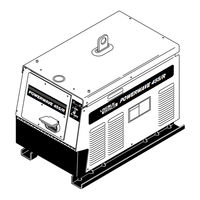
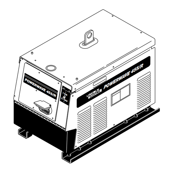
Lincoln Electric POWER WAVE SVM156-A Service Manual (150 pages)
Lincoln Electric Welder User Manual
Brand:
Lincoln Electric
| Category:
Welding System
| Size: 5 MB
Table of Contents
- Master for All Sections -
6
Safety
2
California Proposition 65 Warnings
2
Electric and Magnetic Fields
2
Electric Shock Can Kill
3
Fumes and Gases
3
Table of Contents
6
Installation
8
Technical Specifications
8
Safety Precautions
10
Select Suitable Location
10
Lifting
10
Stacking
10
Machine Grounding
10
High Frequency Protection
10
Input Connection
11
Input Fuse and Supply Wire Considerations
11
Input Voltage Change over (for Multiple Input Voltage Machines Only
12
Welding with Multiple Power Waves
12
Electrode and Work Cable Connections
13
Negative Electrode Polarity
13
Voltage Sensing
14
Electrode Voltage Sensing
15
Work Voltage Sensing
15
Power Wave / Power Feed Wire Feeder Interconnections
15
Control Cable Specifications
15
External I/O Connector
15
Control Board Dip Switch
16
Dip Switch Settings and Locations
16
Feed Head Board Dip Switch
16
Devicenet/Gateway Board Dip Switch, Bank (S2
17
Operation
19
Operation Section
19
Operation
20
Safety Precautions
20
Operation
21
Graphic Symbols
21
General Description
22
Design Features and Advantages
22
Recommended Processes and Equipment
23
Duty Cycle and Time Period
23
Limitations
23
Recommended Equipment
23
Recommended Processes
23
Required Equipment
23
Case Front Controls
24
Wave Control
25
Welding Mode Descriptions
25
Constant Voltage Welding
25
Pulse Welding
26
STT Welding
27
Accessories Section
29
Factory Installed
30
Field Installed
30
Optional Equipment
30
Accessories
30
Maintenance Section
31
Routine and Periodic Maintenance
32
Maintenance
33
Theory of Operation
35
Theory of Operation Section
35
Theory of Operation
36
General Description
36
Input Voltage and Precharge
37
Switch Boards and Main Transformer
38
DC Bus Board, Power Board, Feed Head Board, Gateway Board and Voltage Sense Board
39
Control Board
41
Output Rectifier, Output Choke and STT Chopper Board
42
Overcurrent Protection
43
Protective Circuits
43
Thermal Protection
43
Under/Over Voltage Protection
43
Insulated Gate Bipolar Transistor (IGBT) Operation
45
Pulse Width Modulation
46
Maximum Output
46
Minimum Output
46
Troubleshooting & Repair
47
How to Use Troubleshooting Guide
48
Troubleshooting & Repair
48
PC Board Troubleshooting Procedures
49
ELECTRIC SHOCK Can Kill
49
Troubleshooting Guide
50
Input Filter Capacitor Discharge Procedure
55
Materials Needed
55
Test Procedure
56
Switch Board Test
57
Test Description
60
Input Rectifier Test
60
Input Contactor Test
63
Input Contactor
64
DC Bus Power Supply PC Board Test
66
ELECTRIC SHOCK Can Kill
68
Power Board Test
69
Input Board Test
72
STT Chopper Board Test
76
Control Pc Board
77
Power Pc Board
77
Power Wave Current Transducer Test
79
Control Board
80
Current Transducer
80
STT Current Transducer Test
83
Output Rectifier Test
87
Auxiliary Transformer No. 1 Test
89
ELECTRIC SHOCK Can Kill
91
Auxiliary Transformer No. 2 Test
92
Input Rectifier Removal and Replacement
94
Removal Procedure
95
Replacement Procedure
95
Input Contactor Removal and Replacement
96
Auxiliary Transformer No. 1 Removal and Replacement Procedure
98
Auxiliary Transformer No. 2 Removal and Replacement Procedure
101
Control, Feed Head, or Voltage Sense PC Board Removal and Replacement
104
Gateway PC Board Removal and Replacement
108
STT Current Transducer Removal and Replacement
110
Power Wave Current Transducer Removal and Replacement
113
Output Rectifier, STT Chopper Board and Rectifier Module Removal and Replacement
116
Switch Board and Filter Capacitor Removal and Replacement
120
Retest after Repair
123
Electrical Diagrams
125
Electrical Diagrams
126
Wiring Diagram (Code 10675
126
Power Wave
126
Schematic - Complete Machine (Code 10675
128
Schematic-Complete Machine Code 10676
129
Schematic - Chopper PC Board
130
Schematic-Devicenet/Gateway Pc Board
132
Schematic - Control PC Board
134
Schematic - Digital Power Supply PC Board
136
Schematic - Feedhead PC Board #1
138
Schematic- Feedhead Pc Board #2
139
Schematic- Feedhead Pc Board #3
140
Schematic - Input PC Board
142
Schematic -Switch Pc Board
144
Schematic - Voltage Sense PC Board
146
Schematic - 40 VDC Bus PC Board
148
Advertisement
Advertisement
Related Products
Lincoln Electric MULTI-SOURCE SVM155-A
Lincoln Electric MULTI-WELD SVM151-A
Lincoln Electric POWER MIG SVM157-A
Lincoln Electric POWER WAVE 355/405 SVM159-A
Lincoln Electric COMMANDER SVM153-A
Lincoln Electric INVERTEC SVM158-A
Lincoln Electric INVERTEC SVM129-B
Lincoln Electric POWER MIG SVM160-B
Lincoln Electric RANGER SVM120-A
Lincoln Electric CLASSIC III SVM 137-A
Lincoln Electric Categories
Welding System
Welding Accessories
Flashlight
Wire Feeders
Portable Generator
More Lincoln Electric Manuals
Login
Sign In
OR
Sign in with Facebook
Sign in with Google
Upload manual
Upload from disk
Upload from URL