Sign In
Upload
Manuals
Brands
Liebert Manuals
Humidifier
8 Tons
Liebert 8 Tons Manuals
Manuals and User Guides for Liebert 8 Tons. We have
1
Liebert 8 Tons manual available for free PDF download: User Manual
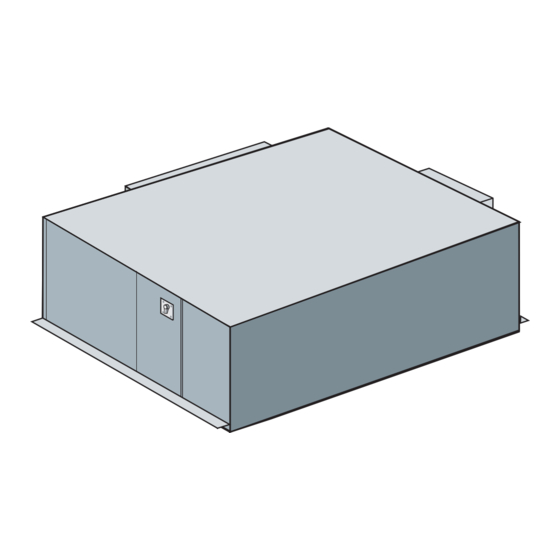
Liebert 8 Tons User Manual (72 pages)
8 Tons, 50 & 60Hz
Brand:
Liebert
| Category:
Humidifier
| Size: 4 MB
Table of Contents
Table of Contents
3
Model Number Nomenclature
7
1 Product Features
9
Standard Product Features
9
Controls
9
Evaporator System Components
9
Condensing Unit Components
9
Optional Equipment
10
Canister Humidifier
10
Electric Reheat
10
SCR Electric Reheat
10
Hot Gas Bypass (Condensing Units)
10
Free-Cooling Coil (GLYCOOL)
10
Smoke Detector
10
Firestat
10
Filter Clog
10
Ancillary (Ship Loose Accessories)
11
Single Point Power Kit
11
Refrigerant Line Sweat Adapter Kits
11
Return Air Filter Box with Duct Collar Kit
11
Condensate Pump Kit
11
Remote Monitoring and Control
11
Remote Sensors
11
2 Site Preparation and Installation
12
Installation Considerations
12
Room Preparation
12
Table 1 Application Limits, Evaporator and Chilled-Water Units
12
Table 2 Application Limits, Indoor and Outdoor Air-Cooled Condensing Units
12
Table 3 Application Limits, Indoor Water/Glycol-Cooled Condensing Units
12
Table 1
12
Location Considerations
13
Figure 1 System Configurations-Air Cooled Systems
14
Figure 2 System Configurations-Water/Glycol Systems
14
System Weights
15
Equipment Inspection Upon Receipt
15
Figure 3 System Configurations-Chilled Water Systems
15
Table 4
15
Table 4 Unit Weights
15
Installing the Evaporator or Chilled-Water Units
16
Figure 4 Threaded Rod and Hardware Kit Installation
16
Close Coupled Installations
17
Figure 5 Close Coupled Installation
17
Evaporator Air Distribution
18
Table 5 Evaporator External Static Pressure (60) at 3750 CFM (6371 CMH)
18
Figure 6 Drain Installation
19
Piping Connections and Coolant Requirements
19
Figure 7 Condensate Pump Installation
20
Figure 8 General Arrangement Diagram - Chilled-Water Systems
21
Figure 9 Refrigerant Piping Diagram
22
Table 6 Recommended Refrigerant Line Sizes
22
8-Ton Unit Refrigerant Charge
23
Line Charges (Field Piping)
23
Quick Connect Fittings
23
Table 7
23
Table 8 Line Charges (Field Piping)
23
Table 9 Refrigerant Quick Connect Sizes and Torque
23
Figure 10 Evaporator or Chilled-Water Unit Dimensional Data
24
Electrical Connections, Evaporator or Chilled-Water Unit
25
Power Connections
25
Figure 11 Evaporator Unit Electrical Connections
26
Indoor Air-Cooled Centrifugal Fan Condensing Unit Installation
27
Location Considerations
27
Ducting
27
General Considerations
27
Piping Connections
28
Figure 12 Piping Connections - Indoor Air-Cooled Centrifugal Fan Condensing Unit
28
Electrical Connections - Condensing Unit
28
Control Connections
28
Figure 13 Indoor Air-Cooled Centrifugal Condensing Unit Dimensions and Pipe Connections
29
Figure 14 Indoor Air-Cooled Centrifugal Condenser Electrical Connections
30
Outdoor Air-Cooled Condensing Unit Installation
31
Location Considerations
31
Piping Connections
31
Electrical Connections
31
Figure 15 Electrical Field Connections - Outdoor Condensing Unit
32
Figure 16 Footprint Dimensions - Outdoor Condensing Unit
33
Figure 17 Piping and Electrical Connections - Outdoor Condensing Unit
34
Indoor Water- and Glycol-Cooled Condensing Unit Installation
35
Location Considerations
35
Piping Connections
35
Electrical Connections
35
Figure 18 Indoor Water/Glycol Condensing Unit Dimensional Data
36
Figure 19 Indoor Water/Glycol Condensing Unit Electrical Field Connections
37
Figure 20 System Piping with Indoor Water/Glycol-Cooled Condensing Unit
38
Optional Equipment Piping
39
Free-Cooling Coil (GLYCOOL)
39
Figure 21 Optional Free Cooling Coil (3-Way Valve) on Water/Glycol Units
39
Figure 22 Optional Free Cooling Coil (3-Way Valve) on Air-Cooled Units
40
Checklist for Completed Installation
41
3 Microprocessor Control
42
Feature Overview
42
Figure 23 Wall Box
42
Main Menu <Menu
43
Setpoints
44
Status
44
Active Alarms
44
Alarm History
44
Table 10 Default Setpoints and Allowable Ranges
44
Time
45
Date
45
Setback
45
Setup Operation
45
Restart Time Delay
45
Table 11 Night and Weekend Setback Plan
45
3.10.2 C/F Degrees
46
3.10.3 Humidity Control Method
46
3.10.4 Lead Compressor
46
3.10.5 Show DIP Switch
46
Valve Time (for Systems with a Modulating Chilled-Water Valve)
46
CW Flush (for Systems with a Modulating Chilled-Water Valve)
47
Change Passwords
47
Calibrate Sensors
47
Alarm Enable
47
Table 12 Setup Functions, Default Values and Allowable Ranges
47
Alarm Time Delay
48
Common Alarm Enable
48
Custom Alarms
48
Table 13 Alarm Default Time Delays
48
Table 15 Switch Settings (Wallbox Board)
49
Custom Text
49
Table 14 Equipment Switch Settings (Unit Control Board)
49
Nonvolatile Memory
49
Run Diagnostics
50
Test Outputs
50
Test Inputs
50
Figure 24 Control Menu
51
Figure 25 Control Board (Inside Evaporator)
52
Figure 26 Wall Box Board
52
4 System Performance Microprocessor Controls
53
Control Type Response Proportional Control
53
Cooling
53
Multi-Step Cooling, Compressorized Direct Expansion (DX) Systems
53
Chilled-Water Cooling (8 Ton)
53
GLYCOOL Cooling (8 Ton)
53
Reheat
53
Electric Reheat - Staged
53
SCR Electric Reheat
53
Dehumidification / Humidification Percent Required
54
Staged Dehumidification, Compressorized Direct Expansion (DX) Systems
54
Humidification Operation
54
Dehumidification Lockout
54
Load Control Features
54
Communications
54
5 Alarms
55
Alarms: Definitions and Troubleshooting
55
Custom Alarms
55
High Head Pressure
55
Humidity
56
Temperature
56
Humidifier Problem Alarm
56
High-Water Alarm
56
Loss of Power
56
Short Cycle
56
Optional/Custom Alarms
57
Change Filter
57
Firestat
57
Smoke Detector
57
6 System Operation , Testing , and Maintenance
58
System Testing
58
Environmental Control Functions
58
Cooling
58
Heating
58
Humidification
58
Dehumidification
58
Remote Shutdown
58
Maintenance and Component Operation
59
Electric Panel
59
Filters
59
Blower System
59
Air Distribution
59
Electric Reheat
60
Refrigeration System
60
Suction Pressure
60
Air-Cooled Condensing Units
60
Table 16 Typical Discharge Pressures
60
Glycol Solution Maintenance
61
Replacement Procedures
62
Steam Generating Humidifier - Operation Procedures
63
Circuit Board Adjustments
64
Table 17 Humidifier Control Board DIP Switch Settings
64
7 Maintenance Inspection Checklist
65
8 Troubleshooting
66
Table 18 Troubleshooting
66
Advertisement
Advertisement
Related Products
Liebert 8 bay
Liebert Hiross Himod 80UC
Liebert Hiross Himod 85UC
Liebert Hiross Himod 80OC
Liebert Hiross Himod 85OC
Liebert 50 & 60Hz
Liebert SGH Steam
Liebert Categories
UPS
Air Conditioner
Power Supply
Surge Protector
Chiller
More Liebert Manuals
Login
Sign In
OR
Sign in with Facebook
Sign in with Google
Upload manual
Upload from disk
Upload from URL