Sign In
Upload
Manuals
Brands
LGC Wireless Manuals
Switch
InterReach Unison
LGC Wireless InterReach Unison Manuals
Manuals and User Guides for LGC Wireless InterReach Unison. We have
1
LGC Wireless InterReach Unison manual available for free PDF download: Installation & Operation Manual
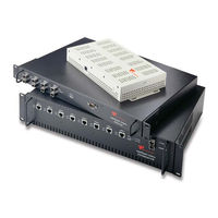
LGC Wireless InterReach Unison Installation & Operation Manual (232 pages)
Brand:
LGC Wireless
| Category:
Switch
| Size: 2 MB
Table of Contents
Table of Contents
5
Limited Warranty
3
General Information
15
SECTION 1 General Information
15
Firmware Release
16
Purpose and Scope
16
Conventions in this Manual
17
Table 1-1 Type Style Conventions
17
Acronyms in this Manual
18
Standards Conformance
20
Related Publications
20
Interreach Unison System Description
21
System Hardware
23
Figure 2-1 Unison System Hardware
23
System OA&M Capabilities
24
Figure 2-2 OA&M Communications
24
Table 2-1 Adminmanager and Opsconsole Functional Differences
25
Table 2-2 Adminmanager and Opsconsole Connectivity Differences
26
Figure 2-3 Local System Monitoring and Reporting
27
OA&M Software
27
Figure 2-5 Alarm Source
29
Figure 2-6 Alarm Sense
29
Using Alarm Contacts
29
System Connectivity
31
Figure 2-7 Unison's Double Star Architecture
31
System Operation
32
Figure 2-8 Downlink (Base Station to Wireless Devices)
32
Figure 2-9 Uplink (Wireless Devices to Base Station)
32
System Specifications
33
Table 2-3 System Specifications
33
Environmental Specifications
34
Interreach Unison Wavelength and Laser Power
34
Table 2-4 Interreach Unison Wavelength and Laser Power
34
Table 2-5 Environmental Specifications
34
Operating Frequencies
35
Table 2-6 Operating Frequencies
35
RF End-To-End Performance
36
Table 2-7 Cellular RF End-To-End Performance
36
Table 2-8 Iden RF End-To-End Performance
36
Table 2-10 DCS RF End-To-End Performance
37
Table 2-9 GSM/EGSM RF End-To-End Performance
37
Table 2-11 PCS RF End-To-End Performance
38
Table 2-12 UMTS RF End-To-End Performance
38
Table 2-13 AWS RF End-To-End Performance
39
Unison Main Hub
41
Main Hub Front Panel
42
Figure 3-3 Main Hub Front Panel
42
Communications RS-232 Serial Connector
43
Optical Fiber Uplink/Downlink Ports
43
LED Indicators
44
Table 3-2 Main Hub Port LED States
46
Main Hub Rear Panel
47
Figure 3-4 Main Hub Rear Panel
47
Main Hub Rear Panel Connectors
48
Table 3-3 9-Pin D-Sub Connector Functions
48
Main Hub Specifications
49
Faults, Warnings, and Status Messages
50
Description
50
View Preference
50
Unison Expansion Hub
53
Expansion Hub Front Panel
54
Figure 4-3 Expansion Hub Front Panel
54
Connectors
55
LED Indicators
55
Optical Fiber Uplink/Downlink Connectors
55
Table 4-1 Expansion Hub Unit Status and DL/UL Status LED States
56
Table 4-2 Expansion Hub Port LED States
57
Expansion Hub Rear Panel
58
Figure 4-4 Expansion Hub Rear Panel
58
Table 4-3 DB-9 Pin Connectors
58
Faults, Warnings, and Status Messages
59
Expansion Hub Specifications
60
Unison Remote Access Unit
61
Figure 5-2 Remote Access Unit Block Diagram
62
Remote Access Unit Connectors
63
SMA Connector
63
Table 5-1 Frequency Bands Covered by Unison Raus
63
LED Indicators
64
RJ-45 Connector
64
Table 5-2 Remote Access Unit LED States
64
Faults, Warnings, and Status Messages
65
Remote Access Unit Specifications
65
Raus in a Dual Band System
66
Designing a Unison Solution
67
Maximum Output Power Per Carrier at RAU
69
800 Mhz Cellular
70
Table 6-1 Cellular Power Per Carrier
70
800 Mhz Iden/Smr
71
Table 6-2 Iden/Smr Power Per Carrier
71
900 Mhz GSM and EDGE
72
Table 6-3 GSM and EDGE Power Per Carrier
72
1800 Mhz DCS
73
Table 6-4 DCS Power Per Carrier
73
1900 Mhz PCS
74
Table 6-5 PCS Power Per Carrier
74
2.1 Ghz AWS
75
Ghz UMTS
75
Table 6-6 UMTS Power Per Carrier
75
Table 6-7 AWS Power Per Carrier
75
Table 6-8 900 Mhz Paging/Smr/Iden
76
Table 6-9 800 Mhz Cellular/1900 Mhz PCS Power Per Carrier
76
Estimating RF Coverage
78
Figure 6-1 Determining Path Loss between the Antenna and the Wireless Device
78
Table 6-10 Coaxial Cable Losses (Lcoax)
78
Path Loss Equation
79
Table 6-11 Average Signal Loss of Common Building Materials
79
Coverage Distance
80
Table 6-12 Estimated Path Loss Slope for Different In-Building Environments
80
Table 6-13 Frequency Bands and the Value of the First Term in Equation
81
Table 6-14 Approximate Radiated Distance from Antenna for 800 Mhz Cellular Applications
81
Table 6-15 Approximate Radiated Distance from Antenna for 800 Mhz Iden Applications
82
Table 6-16 Approximate Radiated Distance from Antenna for 900 Mhz GSM Applications
82
Table 6-17 Approximate Radiated Distance from Antenna for 900 Mhz EGSM Applications
82
Table 6-18 Approximate Radiated Distance from Antenna for 1800 Mhz DCS Applications
83
Table 6-19 Approximate Radiated Distance from Antenna for 1800 Mhz CDMA (Korea) Applications
83
Table 6-20 Approximate Radiated Distance from Antenna for 1900 Mhz PCS Applications
83
Table 6-21 Approximate Radiated Distance from Antenna for 2.1 Ghz UMTS Applications
83
Table 6-22 Approximate Radiated Distance from Antenna for 1.7/2.1 Ghz AWS Applications
84
Examples of Design Estimates
85
System Gain
89
System Gain (Loss) Relative to Sctp Cable Length
89
Table 6-23 System Gain (Loss) Relative to Sctp Cable Length
89
Link Budget Analysis
90
Elements of a Link Budget for Narrowband Standards
90
Narrowband Link Budget Analysis for a Microcell Application
93
Table 6-25 Narrowband Link Budget Analysis: Downlink
93
Table 6-26 Narrowband Link Budget Analysis: Uplink
94
Elements of a Link Budget for CDMA Standards
95
Table 6-27 Distribution of Power Within a CDMA Signal
95
Table 6-28 Additional Link Budget Considerations for CDMA
96
CDMA Link Budget Analysis for a Microcell Application
98
Table 6-29 CDMA Link Budget Analysis: Downlink
98
Table 6-30 CDMA Link Budget Analysis: Uplink
100
Considerations for Re-Radiation (Over-The-Air) Systems
101
Optical Power Budget
102
Connecting a Main Hub to a Base Station
103
Figure 6-2 Connecting Main Hubs to a Simplex Base Station
103
Attenuation
104
Figure 6-3 Main Hub to Duplex Base Station or Repeater Connections
104
Uplink Attenuation
105
Figure 6-4 ALC Operation
107
RAU Attenuation and ALC
107
Table 6-31 Frequency Bands Adjacent to System Configured Bands
109
Designing for a Neutral Host System
110
Installing Unison
113
Installation Requirements
113
SECTION 7 Installing Unison
113
Cable and Connector Requirements
114
Component Location Requirements
114
Distance Requirements
114
Multiple Operator System Recommendations
114
Table 7-1 Unison Distance Requirements
115
Safety Precautions
116
General Safety Precautions
116
Installation Guidelines
116
Fiber Port Safety Precautions
117
Preparing for System Installation
118
Installation Checklist
118
Pre-Installation Inspection
118
Table 7-2 Installation Checklist
118
Optional Accessories
121
Table 7-3 Tools and Materials Required for Component Installation
121
Table 7-4 Optional Accessories for Component Installation
121
Tools and Materials Required
121
7.4 Unison Component Installation Procedures
123
Unison Component Installation Procedures
123
Figure 7-1 Mounting Bracket Detail
125
Installing a Main Hub
125
Installing a Main Hub in a Rack
125
Installing an Optional Cable Manager in the Rack
125
Connecting the Fiber Cables to the Main Hub
126
Table 7-5 Troubleshooting Main Hub Leds During Installation
128
Installing an Expansion Hub in a Rack
130
Installing an Expansion Hub in a Wall-Mounted Rack
130
Installing Expansion Hubs
130
Figure 7-2 Mounting Bracket Installation
131
Installing an Optional Cable Manager in the Rack
131
Powering on the Expansion Hub
131
Connecting the Fiber Cables to the Expansion Hub
132
Connecting the Sctp Cables
133
Troubleshooting Expansion Hub Leds During Installation
134
Installing Passive Antennas
135
Installing Raus
135
Figure 7-3 800 Mhz Spectrum
136
Figure 7-4 Guideline for Unison RAU Antenna Placement
136
Connecting the Antenna to the RAU
137
Connecting the Sctp Cable
137
Table 7-7 Troubleshooting RAU Leds During Installation
138
Troubleshooting RAU Leds During Installation
138
Installing a Dual-Band RAU Configuration
139
Installing Raus in a Dual Band System
139
Figure 7-5 Dual Band RAU Configuration
140
Connecting the Antenna to the Dual Band Diplexer
141
Using a Cat-5 Extender
141
Configuring the System
142
Table 7-8 Maximum/Minimum Cable Lengths
142
Configuring the Installed System
143
Splicing Fiber Optic Cable
145
Fusion Splices
145
Fusion Splicing of Fiber and Pigtail
145
Figure 7-7 Simplex Base Station to a Main Hub
147
Connecting a Main Hub to an In-Building Base Station
147
Figure 7-8 Duplex Base Station to a Main Hub
148
Connecting a Main Hub to a Roof-Top Antenna
149
Connecting a Main Hub to Multiple Base Stations
149
Figure 7-9 Connecting a Main Hub to Multiple Base Stations
149
Connecting Multiple Main Hubs
150
Connecting Multiple Main Hubs to a Simplex Repeater or Base Station
150
Interfacing a Main Hub to a Base Station or a Roof-Top Antenna
147
Connecting Multiple Main Hubs to a Duplex Repeater or Base Station
152
Figure 7-11 Connecting Two Main Hubs to a Duplex Repeater or Base Station
153
Connecting Contact Alarms to a Unison System
154
Table 7-9 Alarm Types
154
Alarm Source
155
Figure 7-12 Connecting Metroreach to Unison
155
Figure 7-13 Using a BTS to Monitor Unison
156
Figure 7-14 Using a BTS and Opsconsole to Monitor Unison
157
Alarm Sense
158
Figure 7-15 Connecting Lgcell to Unison
158
Figure 7-16 Alarm Sense Contacts
158
Alarm Cables
161
Figure 7-17 5-Port Alarm Daisy-Chain Cable
161
Alarm Monitoring Connectivity Options
163
Direct Connection
163
Figure 7-19 OA&M Direct Connection
163
Modem Connection
164
Figure 7-21 OA&M Connection Using an RS-232 Port Expander
165
Port Expander Connection
165
Figure 7-22 OA&M Connection Using a POTS Line Sharing Switch
166
Figure 7-23 Cascading Line Sharing Switches
166
POTS Line Sharing Switch Connection
166
Ethernet and ENET/RS-232 Serial Hub Connection
167
Figure 7-25 Network Interface Unit (NIU) Configuration Options
168
Network Interface Unit (NIU)
168
Figure 7-26 Multiple Unison Systems Monitored by a Single Network Management System
169
Replacing Unison Components
171
Replacing an RAU
171
Replacing an Expansion Hub
173
Replacing a Main Hub
174
Maintenance, Troubleshooting, and Technical Assistance
177
Service
177
Maintenance
178
Troubleshooting
179
Troubleshooting Using Adminmanager
180
Fault Indications
181
Table 9-1 Faults Reported by the Main Hub
182
Table 9-2 Faults Reported by the Expansion Hub
186
Table 9-3 Faults Reported by the RAU
192
Table 9-4 Warnings Reported by the Main Hub
193
Warning Indications
193
Table 9-5 Warnings Reported by the Expansion Hub
196
Table 9-6 Warnings Reported by the RAU
197
Table 9-7 Status Messages Reported by the Main Hub
198
Table 9-8 Status Messages Reported by the Expansion Hub
200
Table 9-9 Status Messages Reported by the RAU
202
Table 9-10 Troubleshooting Main Hub Port Leds During Normal Operation
203
Troubleshooting Using Leds
203
Table 9-11 Troubleshooting Main Hub Status Leds During Normal Operation
204
Table 9-12 Troubleshooting Expansion Hub Port Leds
205
Table 9-13 Troubleshooting Expansion Hub Status Leds
206
Troubleshooting CAT-5/5E/6
207
Table 9-14 Summary of Cat-5/5E/6 Cable Wiring Problems
208
Technical Assistance
209
APPENDIX A Cables and Connectors
211
CAT-5E/6 Cable (Sctp
211
Table A-1 CAT-5E/6 Twisted Pair Assignment
211
Figure A-1 Wiring Map for Cat-5E/6 Cable
212
Coaxial Cable
213
Fiber Optical Cables
213
Figure A-2 Standard Modem Cable Pinout
213
Standard Modem Cable
213
DB-25 to DB-9 Null Modem Cable
215
Figure A-4 DB-25 Male to DB-9 Female Null Modem Cable Diagram
215
Table A-3 DB-25 Male to DB-9 Female Null Modem Cable Pinout
215
APPENDIX B Compliance
217
Unison System Approval Status
217
Human Exposure to RF
219
APPENDIX C Changes and New Capabilities
221
New in Rev. J of Manual
221
New in Rev. H. of Manual
221
New in Rev. G of Manual
222
New in Rev. F of Manual
222
New in Rev. E of Manual
222
New in Rev. D of Manual
222
New in Rev. C of Manual
222
New in Rev. B of Manual
223
APPENDIX D Glossary
225
Advertisement
Advertisement
Related Products
LGC wireless InterReach Fusion
LGC Wireless InterReach Fusion SingleStar
LGC Wireless Categories
Switch
Network Hardware
Receiver
More LGC Wireless Manuals
Login
Sign In
OR
Sign in with Facebook
Sign in with Google
Upload manual
Upload from disk
Upload from URL