
Summary of Contents for LGC wireless InterReach Unison
- Page 1 ® InterReach Unison Installation, Operation, and Reference Manual CONFIDENTIAL D-620003-0-20 Rev J...
- Page 2 This manual is produced for use by LGC Wireless personnel, licensees, and customers. The information contained herein is the property of LGC Wireless. No part of this document may be reproduced or transmitted in any form or by any means, electronic or mechanical, for any purpose, without the express written permission of LGC Wireless.
-
Page 3: Limited Warranty
Licensed Operators LGC Wireless’ equipment is designed to operate in the licensed frequency bands of mobile, cellular, and PCS operators. In the USA, the EU, and most countries this equipment may only be used by the licensee, his authorized agents or those with written authorization to do so. - Page 4 InterReach Unison Installation, Operation, and Reference Manual CONFIDENTIAL D-620003-0-20 Rev J...
-
Page 5: Table Of Contents
....... . 1-6 InterReach Unison System Description ..2-1 SECTION 2 2.1 System Hardware... - Page 6 ........6-38 InterReach Unison Installation, Operation, and Reference Manual...
- Page 7 ....... . . 8-1 InterReach Unison Installation, Operation, and Reference Manual...
- Page 8 Glossary ....... . D-1 APPENDIX D InterReach Unison Installation, Operation, and Reference Manual CONFIDENTIAL...
- Page 9 ........7-24 Figure 7-4 Guideline for Unison RAU Antenna Placement ....7-24 InterReach Unison Installation, Operation, and Reference Manual CONFIDENTIAL D-620003-0-20 Rev J...
- Page 10 Figure A-3 DB-9 Female to DB-9 Female Null Modem Cable Diagram ..A-4 Figure A-4 DB-25 Male to DB-9 Female Null Modem Cable Diagram ..A-5 InterReach Unison Installation, Operation, and Reference Manual CONFIDENTIAL D-620003-0-20 Rev J...
- Page 11 GSM and EDGE Power per Carrier ......6-6 InterReach Unison Installation, Operation, and Reference Manual CONFIDENTIAL...
- Page 12 ........7-6 viii InterReach Unison Installation, Operation, and Reference Manual CONFIDENTIAL...
- Page 13 ..A-4 Table A-3 DB-25 Male to DB-9 Female Null Modem Cable Pinout ... A-5 InterReach Unison Installation, Operation, and Reference Manual CONFIDENTIAL D-620003-0-20 Rev J...
- Page 14 This page is intentionally left blank. InterReach Unison Installation, Operation, and Reference Manual CONFIDENTIAL D-620003-0-20 Rev J...
-
Page 15: General Information
• Section 1.6 Related Publications ........1-6 InterReach Unison Installation, Operation, and Reference Manual... -
Page 16: Firmware Release
This section provides installation procedures and considerations when you are replacing a Unison component in an operating system. • Section 9 Maintenance, Troubleshooting, and Technical Assistance This section contains contact information and troubleshooting tables. InterReach Unison Installation, Operation, and Reference Manual CONFIDENTIAL D-620003-0-20 Rev J... -
Page 17: Conventions In This Manual
Conventions in this Manual • Appendix A Cables and Connectors This appendix contains connector and cable descriptions and requirements, as well as cable pin outs and diagrams. Appendix B Compliance This appendix lists safety and Radio/EMC approvals. • Appendix C Changes and New Capabilities This appendix contains a hardware/firmware/software compatibility. -
Page 18: Acronyms In This Manual
1 milliwatt direct current Digital Communications System downlink EDGE Enhanced Data Rates for Global Evolution EGSM Extended Global Standard for Mobile Communications Expansion Hub gigahertz GPRS General Packet Radio Service InterReach Unison Installation, Operation, and Reference Manual CONFIDENTIAL D-620003-0-20 Rev J... - Page 19 Acronyms in this Manual Acronym Definition Groupe Speciale Mobile (now translated in English as Global Standard for Mobile Communications) hertz intermediate frequency iDEN Integrated Digital Enhanced Network (Motorola variant of TDMA wireless) local area network local oscillator milliamps microcellular base station Main Hub megahertz multi-mode fiber...
-
Page 20: Standards Conformance
• OpsConsole User Manual; LGC Wireless part number 8800-10 • MetroReach Focus Configuration, Installation, and Reference Manual; LGC Wireless part number 8500-10 • LGCell Version 4.0 Installation, Operation, and Reference Manual; LGC Wireless part number 8100-50 • Neutral Host System Planning Guide; LGC Wireless part number 9000-10 •... -
Page 21: Interreach Unison System Description
InterReach Unison System SECTION 2 Description InterReach Unison is an intelligent fiber optic/Cat-5/5E/6 wireless networking system designed to handle both wireless voice and data communications and provide high-quality, ubiquitous, seamless access to the wireless network in any public or pri- vate facility, including: •... - Page 22 • Extensive OA&M capabilities, including fault isolation to the field replaceable unit, automatic reporting of all fault and warning conditions, and user-friendly graphical-user interface OA&M software packages. InterReach Unison Installation, Operation, and Reference Manual CONFIDENTIAL D-620003-0-20 Rev J...
-
Page 23: System Hardware
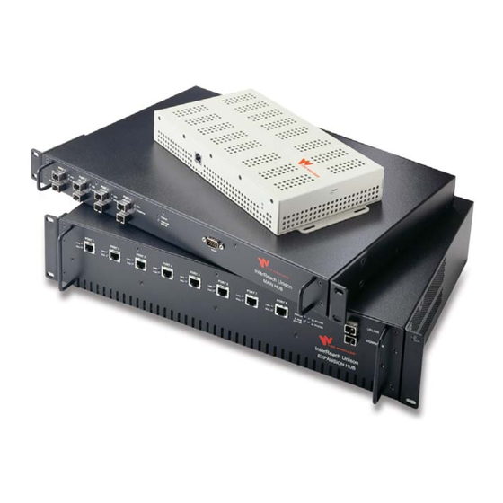
System Hardware System Hardware The InterReach Unison system consists of three modular components: • 19" rack-mountable Main Hub (connects to up to 4 Expansion Hubs) • RF signal conversion to optical on the downlink; optical to RF on the uplink •... -
Page 24: System Oa&M Capabilities
System OA&M Capabilities System OA&M Capabilities The InterReach Unison is microprocessor controlled and contains firmware which enables much of the OA&M functionality. Complete alarming, down to the field replaceable unit (that is, Main Hub, Expansion Hub, Remote Access Unit) and the cabling infrastructure, is available. All events occurring in a system, defined as a Main Hub and all of its associated Expansion Hubs and Remote Access Units, are automatically reported to the Main Hub. -
Page 25: Table 2-1 Adminmanager And Opsconsole Functional Differences
System OA&M Capabilities LGC Wireless offers two OA&M packages: AdminManager and OpsConsole. Both run on a PC/laptop. • AdminManager communicates with one Main Hub, and its downstream units, at a time. Using AdminManager connected locally or remotely, you can configure a newly installed system, change system parameters, perform an end-to-end system test, or query system status. -
Page 26: Table 2-2 Adminmanager And Opsconsole Connectivity Differences
COM1 through COM16 Modem (including RF modem) Ethernet/232 serial hub Yes, if the remote COM port is in the range of COM1 through COM16 Line Sharing Switch after POTS InterReach Unison Installation, Operation, and Reference Manual CONFIDENTIAL D-620003-0-20 Rev J... -
Page 27: Oa&M Software
System OA&M Capabilities 2.2.1 OA&M Software 2.2.1.1 Configuring, Maintaining, and Monitoring Unison Locally Each Main Hub, Expansion Hub, and RAU in the system constantly monitors itself and its downstream units for internal fault and warning conditions. The results of this monitoring are stored in memory and compared against new results. - Page 28 If a fault or warning condi- tion is reported, the OpsConsole graphical user interface indicates the problem. OpsConsole can also send an e-mail and/or page notification to desig- nated recipients. InterReach Unison Installation, Operation, and Reference Manual CONFIDENTIAL D-620003-0-20 Rev J...
-
Page 29: Using Alarm Contacts
System OA&M Capabilities 2.2.2 Using Alarm Contacts You can connect the DB-9 female connector on the rear panel of the Main Hub to a local base station or to a daisy-chained series of Unison, LGCell, and/or MetroReach Focus systems. • When you connect MetroReach Focus or a BTS to Unison, the Unison Main Hub is the output of the alarms (alarm source) and MetroReach Focus or the BTS is the input (alarm sense). - Page 30 System OA&M Capabilities Alarm Sense. Figure 2-6 Unison Main Hub Up to 5 LGCell Main Hubs 5-port Alarm Daisy-Chain Cable Alarm Sense Alarm Source Alarm Sense Adapter Cable Alarm Source 2-10 InterReach Unison Installation, Operation, and Reference Manual CONFIDENTIAL D-620003-0-20 Rev J...
-
Page 31: System Connectivity
System Connectivity System Connectivity The double star architecture of the Unison system, illustrated in Figure 2-7, provides excellent system scalability and reliability. The system requires only one pair of fibers for eight antenna points. This makes any system expansion, such as adding an extra antenna for additional coverage, potentially as easy as pulling an extra twisted pair. -
Page 32: System Operation
The Main Hub sends to four) via optical fiber uplink RF signals to a cable and converts base station via coaxial them to RF signals. cable. 2-12 InterReach Unison Installation, Operation, and Reference Manual CONFIDENTIAL D-620003-0-20 Rev J... -
Page 33: System Specifications
System Specifications System Specifications System Specifications Table 2-3 Parameter Main Hub Expansion Hub Remote Access Unit RF Connectors 2 N-type, female 8 shielded RJ-45, female 1 shielded RJ-45, female (Cat-5/5E/6) (Cat-5/5E/6) 1 SMA, male (coaxial) External Alarm Con- 1 9-pin D-sub, female 1 9-pin D-sub, female —... -
Page 34: Interreach Unison Wavelength And Laser Power
–25° to +45°C (–13° to +113°F) Non-operating Temperature –20° to +85°C (–4° to +185°F) –25° to +85°C (–13° to +185°F) Operating Humidity; non-condensing 5% to 95% 5% to 95% 2-14 InterReach Unison Installation, Operation, and Reference Manual CONFIDENTIAL D-620003-0-20 Rev J... -
Page 35: Operating Frequencies
System Specifications 2.5.3 Operating Frequencies Operating Frequencies Table 2-6 RF Passband Freq. Unison Band Band Description Downlink (MHz) Uplink (MHz) PCS6 A, D & B Band 1930–1965 1850–1885 (35 MHz) PCS7 D,B,E & F Band 1945–1975 1865–1895 (30 MHz) PCS8 E, F &... -
Page 36: Rf End-To-End Performance
The system gain is adjustable in 1 dB steps from 0 to 15 dB, and the gain of each RAU can be attenuated 10 dB in one step. 2-16 InterReach Unison Installation, Operation, and Reference Manual CONFIDENTIAL D-620003-0-20 Rev J... -
Page 37: Table 2-9 Gsm/Egsm Rf End-To-End Performance
System Specifications GSM/EGSM 900 MHz GSM/EGSM RF End-to-End Performance Table 2-9 2 km of SMF 1 km of MMF Typical Typical Parameter Downlink Uplink Downlink Uplink Average gain with 75 m Cat-5/5E/6 at 25°C (77°F)* 15 dB 15 dB 15 dB 15 dB Ripple with 75 m Cat-5/5E/6 3 dB... -
Page 38: Table 2-11 Pcs Rf End-To-End Performance
*The system gain is adjustable in 1 dB steps from 0 to 15 dB, and the gain of each RAU can be attenuated 10 dB in one step. – ** For Japan, see separate addendum Japan Specification Document. 2-18 InterReach Unison Installation, Operation, and Reference Manual CONFIDENTIAL D-620003-0-20 Rev J... -
Page 39: Table 2-13 Aws Rf End-To-End Performance
System Specifications AWS 1.7/2.1 GHz AWS RF End-to-End Performance Table 2-13 2 km of SMF 1 km of MMF Typical Typical Parameter Downlink Uplink Downlink Uplink Average gain with 75 m Cat-5/5E/6 at 25°C (77°F) * 15 dB 15 dB 15 dB 15 dB Ripple with 75 m Cat-5/5E/6... - Page 40 System Specifications 2-20 InterReach Unison Installation, Operation, and Reference Manual CONFIDENTIAL D-620003-0-20 Rev J...
-
Page 41: Unison Main Hub
The Main Hub also receives status information from the Expansion Hubs and all RAUs via the fiber optic cable. Figure 3-2 shows a detailed view of the major RF and optical functional blocks of the Main Hub. Main Hub Block Diagram Figure 3-2 InterReach Unison Installation, Operation, and Reference Manual CONFIDENTIAL D-620003-0-20 Rev J... -
Page 42: Main Hub Front Panel
• One LED for unit power status (labeled POWER • One LED for unit status (labeled MAIN HUB STATUS One 9-pin D-sub male connector for system communication and diagnostics using a PC/laptop or modem (labeled RS-232 InterReach Unison Installation, Operation, and Reference Manual CONFIDENTIAL D-620003-0-20 Rev J... -
Page 43: Optical Fiber Uplink/Downlink Ports
Main Hub Front Panel 3.1.1 Optical Fiber Uplink/Downlink Ports The optical fiber uplink/downlink ports transmit and receive optical signals between the Main Hub and up to four Expansion Hubs using industry-standard SMF or MMF cable. There are four fiber ports on the front panel of the Main Hub; one port per Expansion Hub. -
Page 44: Led Indicators
E-HUB/RAU If the LEDs do not display as above, refer to Table 3-1 on page 3-5, Table 3-2 on page 3-6, and/or Section 9 for troubleshooting using the LEDs. InterReach Unison Installation, Operation, and Reference Manual CONFIDENTIAL D-620003-0-20 Rev J... - Page 45 Main Hub Front Panel Unit Status LEDs The Main Hub status LEDs can be in one of the states shown in Table 3-1. These LEDs can be: steady green steady red blinking green/red (alternating green/red) There is no off state when the unit’s power is on. NOTE: AdminManager or OpsConsole must be used for troubleshooting the system.
-
Page 46: Table 3-2 Main Hub Port Led States
• The Expansion Hub is disconnected. Green • The Expansion Hub is connected. LINK E-HUB/RAU • A fault or lockout was reported by the Expansion Hub or any connected RAU. InterReach Unison Installation, Operation, and Reference Manual CONFIDENTIAL D-620003-0-20 Rev J... -
Page 47: Main Hub Rear Panel
Main Hub Rear Panel Main Hub Rear Panel Main Hub Rear Panel Figure 3-4 Power On/Off switch AC power cord connector Fan exhaust vent One 9-pin D-sub female connector for alarm contact monitoring (labeled DIAGNOSTIC 1 Two N-type, female connectors: •... -
Page 48: Main Hub Rear Panel Connectors
DC power UPLINK DOWNLINK feed from the base station. If DC power is present, a DC block must be used or the hub may be damaged. InterReach Unison Installation, Operation, and Reference Manual CONFIDENTIAL D-620003-0-20 Rev J... -
Page 49: Main Hub Specifications
Main Hub Specifications Main Hub Specifications Main Hub Specifications Table 3-4 Specification** Description × × Enclosure Dimensions (H 44.5 mm × 438 mm × 305 mm (1.75 in. × 17.25 in. × 12 in.) Weight < 3 kg (< 6.5 lb) Operating Temperature** 0°... -
Page 50: Faults, Warnings, And Status Messages
• page 9-22 for Main Hub status messages. • page 9-27 for troubleshooting Main Hub LEDs. 3.4.2 View Preference AdminManager 2.04 or higher allows you to select what type of events to be dis- played. 3-10 InterReach Unison Installation, Operation, and Reference Manual CONFIDENTIAL D-620003-0-20 Rev J... - Page 51 Faults, Warnings, and Status Messages To modify the setting, select View Preference and select the desired choice. You can change the setting either while connected to a system or offline. If there is a con- nection to a system, after the you click , AdminManager refreshes and updates the tree view according to the new setting.
- Page 52 Faults, Warnings, and Status Messages This page is intentionally left blank. 3-12 InterReach Unison Installation, Operation, and Reference Manual CONFIDENTIAL D-620003-0-20 Rev J...
-
Page 53: Unison Expansion Hub
Also, the Expansion Hub receives RAU status information via the Cat-5/5E/6 cable and sends it and its own status informa- tion to the Main Hub via the fiber optic cable. Expansion Hub Block Diagram Figure 4-2 From Main Hub To RAU InterReach Unison Installation, Operation, and Reference Manual CONFIDENTIAL D-620003-0-20 Rev J... -
Page 54: Expansion Hub Front Panel
One fiber optic port which has two connectors • One standard female SC/APC connector for MMF/SMF output (labeled UPLINK • One standard female SC/APC connector for MMF/SMF input (labeled DOWNLINK InterReach Unison Installation, Operation, and Reference Manual CONFIDENTIAL D-620003-0-20 Rev J... -
Page 55: Connectors
Expansion Hub Front Panel 4.1.1 RJ-45 Connectors The eight RJ-45 connectors on the Expansion Hub are for the Cat-5/5E/6 ScTP cables used to transmit and receive signals to and from RAUs. Use shielded RJ-45 connec- tors on the Cat-5/5E/6 cable. NOTE: For system performance, it is important to use only Cat-5/5E/6 ScTP (screened twisted pair) cable with shielded RJ-45 connectors. -
Page 56: Table 4-1 Expansion Hub Unit Status And Dl/Ul Status Led States
If initially green, then red after 90 seconds, it means that there is no communication with the Main Hub. If red on power up, the uplink laser has failed, replace the Expansion Hub. InterReach Unison Installation, Operation, and Reference Manual CONFIDENTIAL D-620003-0-20 Rev J... -
Page 57: Table 4-2 Expansion Hub Port Led States
Expansion Hub Front Panel Expansion Hub Unit Status and DL/UL Status LED States Table 4-1 LED State Indicates Green / Red • Expansion Hub is in factory test mode, return it to the factory. POWER DL STATUS E-HUB STATUS UL STATUS Green / Red Red/ Red •... -
Page 58: Expansion Hub Rear Panel
+5V through a 10K Ohm resistor. Input to micro controller ALARM1 +5V through a 10K Ohm resistor. Input to micro controller) ALARM2 This interface can both generate contact alarms and sense a single external alarm con- tact. InterReach Unison Installation, Operation, and Reference Manual CONFIDENTIAL D-620003-0-20 Rev J... -
Page 59: Faults, Warnings, And Status Messages
Faults, Warnings, and Status Messages Faults, Warnings, and Status Messages This interface monitors the output contact closures from a Universal Power Supply (UPS). Verify the output contact closure state (normally closed or normally open) of the UPS, and set the appropriate contact definition using AdminManager. •... -
Page 60: Expansion Hub Specifications
It is critical to system performance that only SC/APC fiber connectors are used throughout the fiber network, including fiber distribution panels. c. For Japan, see separate addendum - Japan Specification Document. InterReach Unison Installation, Operation, and Reference Manual CONFIDENTIAL D-620003-0-20 Rev J... -
Page 61: Unison Remote Access Unit
Uplink Path: The RAU receives uplink RF signals from a passive RF antenna via coaxial cable. It converts the signals to IF and sends them to an Expansion Hub via Cat-5/5E/6 cable. Also, the RAU sends its status information to the Expansion Hub via the Cat-5/5E/6 cable. InterReach Unison Installation, Operation, and Reference Manual LGC CONFIDENTIAL D-620003-0-20 Rev J... -
Page 62: Figure 5-2 Remote Access Unit Block Diagram
Remote Access Unit Block Diagram Figure 5-2 Antenna InterReach Unison Installation, Operation, and Reference Manual CONFIDENTIAL D-620003-0-20 Rev J... -
Page 63: Remote Access Unit Connectors
Remote Access Unit Connectors The Unison RAUs are manufactured to a specific band or set of bands. Table 5-1 lists the Unison RAUs, the Unison Band, and the frequency band(s) they cover. Frequency Bands covered by Unison RAUs Table 5-1 RF Passband Unison Unison... -
Page 64: Rj-45 Connector
• The RAU is indicating a fault or lockout condition, but communication with the Expansion LINK ALARM Hub is normal. • The RAU is reporting a fault or lockout condition, and it is not able to communicate with LINK ALARM the Expansion Hub. InterReach Unison Installation, Operation, and Reference Manual CONFIDENTIAL D-620003-0-20 Rev J... -
Page 65: Faults, Warnings, And Status Messages
Faults, Warnings, and Status Messages Faults, Warnings, and Status Messages An event is classified as a fault, warning, or status message. • Faults are service impacting. • Warnings indicate a possible service impact. • Status messages are generally not service impacting. NOTE: You can select the type of events AdminManager displays. -
Page 66: Raus In A Dual Band System
An alternative to a diplexer is use dual-port, dual-band antennas shown in Table 5-3. Dual-Port Antenna Configuration Figure 5-3 3 ft. coaxial cable Cat-5/5E/6 from Expansion Hub Unison Antenna Cat-5/5E/6 from Expansion Hub Unison 3 ft. coaxial cable InterReach Unison Installation, Operation, and Reference Manual CONFIDENTIAL D-620003-0-20 Rev J... -
Page 67: Designing A Unison Solution
• Obtain floor plans to determine floor space of building and the wall layout of the proposed areas to be covered. Floor plans are also useful when selecting antenna locations. InterReach Unison Installation, Operation, and Reference Manual CONFIDENTIAL D-620003-0-20 Rev J... - Page 68 The individual elements that must be considered in designing a Unison solution are explained in the following sections. NOTE: Access the LGC Wireless portal at LGCWireless.com for on-line dimensioning and design tools. InterReach Unison Installation, Operation, and Reference Manual...
-
Page 69: Maximum Output Power Per Carrier At Rau
Maximum Output Power Per Carrier at RAU Maximum Output Power Per Carrier at RAU The following tables show the recommended maximum power per carrier out of the RAU SMA connector for different frequencies, formats, and numbers of carriers. These limits are dictated by RF signal quality and regulatory emissions issues. The maximum input power to the Main Hub is determined by subtracting the system gain from the maximum output power of the RAU. -
Page 70: 800 Mhz Cellular
Note: Operation at or above these output power levels may prevent Unison from meeting RF performance specifications or FCC Part 15 and EN55022 emis- sions requirements. Refer to the Unison Installation, Operation, and Reference manual for system design information. InterReach Unison Installation, Operation, and Reference Manual CONFIDENTIAL... -
Page 71: 800 Mhz Iden/Smr
Maximum Output Power Per Carrier at RAU 6.1.2 800 MHz iDEN/SMR iDEN/SMR Power per Carrier Table 6-2 Power per Carrier (dBm) Motient Data iDEN Analog FM CQPSK C4FM No. of 2 km SMF/ 2 km SMF/ 2 km SMF/ 2 km SMF/ 2 km SMF/ Carriers 1 km MMF... -
Page 72: 900 Mhz Gsm And Edge
Note: Operation at or above these output power levels may prevent Unison from meeting RF performance specifications or FCC Part 15 and EN55022 emissions requirements. Refer to the Unison Installation, Operation, and Reference manual for system design informa- tion. InterReach Unison Installation, Operation, and Reference Manual CONFIDENTIAL D-620003-0-20 Rev J... -
Page 73: 1800 Mhz Dcs
Maximum Output Power Per Carrier at RAU 6.1.4 1800 MHz DCS DCS Power per Carrier Table 6-4 Power per Carrier (dBm) No. of EDGE EDGE CDMA Carriers 2 km SMF 1 km MMF 2 km SMF 1 km MMF 2 km SMF/1 km MMF 17.5 17.5 17.5... -
Page 74: 1900 Mhz Pcs
Note: Operation at or above these output power levels may prevent Unison from meeting RF performance specifications or FCC Part 15 and EN55022 emissions requirements. Refer to the Unison Installation, Operation, and Reference manual for system design information. InterReach Unison Installation, Operation, and Reference Manual CONFIDENTIAL... -
Page 75: Ghz Umts
Maximum Output Power Per Carrier at RAU 6.1.6 2.1 GHz UMTS UMTS Power per Carrier** Table 6-6 Power per Carrier (dBm) No. of WCDMA Carriers 2 km SMF/1 km MMF 15.0 max. composite DL 11.0 These PPC numbers assume 2 km of SMF or 1 km of MMF. Note: measurements taken with no baseband clipping. -
Page 76: Table 6-8 900 Mhz Paging/Smr/Iden
18.0 20.0 13.0 16.5 14.0 12.5 14.0 12.5 11.5 15.0 16.5 11.0 13.5 12.0 10.5 12.0 10.5 13.0 13.5 10.0 11.5 10.5 10.5 11.5 12.0 10.0 10.5 10.5 6-10 InterReach Unison Installation, Operation, and Reference Manual CONFIDENTIAL D-620003-0-20 Rev J... - Page 77 Maximum Output Power Per Carrier at RAU 800 MHz Cellular/1900 MHz PCS Power per Carrier (continued) Table 6-9 Recommended Maximum Output Power per Carrier at RAU (dBm) 800 MHz Cellular 1900 MHz PCS TDMA AMPS CDMA TDMA EDGE CDMA 2 km 2 km 1 km 2 km...
-
Page 78: Estimating Rf Coverage
Loss at Loss at Length of Cable 800 MHz 1900 MHz (.195 in. diameter) (dB) (dB) 0.9 m (3 ft) 1.8 m (6 ft) 3.0 m (10 ft) 6-12 InterReach Unison Installation, Operation, and Reference Manual CONFIDENTIAL D-620003-0-20 Rev J... -
Page 79: Path Loss Equation
Estimating RF Coverage 6.2.1 Path Loss Equation Indoor path loss obeys the distance power law in equation (2): Χ PL = 20log(4πd f/c) + PLSlog(d/d where: • PL is the path loss at a distance, d, from the antenna (the distance between the antenna connected to the RAU and the point where the RF signal decreases to the minimum acceptable level at the wireless device). -
Page 80: Coverage Distance
For simplicity, Equation (3), Coverage Distance, can be used to estimate the coverage distance of an antenna connected to an RAU, for a given path loss, frequency, and type of in-building environment. 6-14 InterReach Unison Installation, Operation, and Reference Manual CONFIDENTIAL D-620003-0-20 Rev J... -
Page 81: Table 6-13 Frequency Bands And The Value Of The First Term In Equation
Estimating RF Coverage Table 6-13 gives the value of the first term of Equation (3) (that is, (20log(4πf/c)) for various frequency bands. Frequency Bands and the Value of the first Term in Equation (3) Table 6-13 Band (MHz) Mid-Band Frequency Uplink Downlink (MHz) -
Page 82: Table 6-15 Approximate Radiated Distance From Antenna For 800 Mhz Iden Applications
Approximate Radiated Distance from Antenna Table 6-17 for 900 MHz EGSM Applications Distance from Antenna Facility Meters Feet Open Environment Moderately Open Environment Mildly Dense Environment Moderately Dense Environment Dense Environment 6-16 InterReach Unison Installation, Operation, and Reference Manual CONFIDENTIAL D-620003-0-20 Rev J... -
Page 83: Table 6-18 Approximate Radiated Distance From Antenna For 1800 Mhz Dcs Applications
Estimating RF Coverage Approximate Radiated Distance from Antenna Table 6-18 for 1800 MHz DCS Applications Distance from Antenna Facility Meters Feet Open Environment Moderately Open Environment Mildly Dense Environment Moderately Dense Environment Dense Environment Approximate Radiated Distance from Antenna Table 6-19 for 1800 MHz CDMA (Korea) Applications Distance from Antenna Facility... -
Page 84: Table 6-22 Approximate Radiated Distance From Antenna For 1.7/2.1 Ghz Aws Applications
Approximate Radiated Distance from Antenna Table 6-22 for 1.7/2.1 GHz AWS Applications Distance from Antenna Facility Meters Feet Open Environment Moderately Open Environment Mildly Dense Environment Moderately Dense Environment Dense Environment 6-18 InterReach Unison Installation, Operation, and Reference Manual CONFIDENTIAL D-620003-0-20 Rev J... -
Page 85: Examples Of Design Estimates
Estimating RF Coverage 6.2.3 Examples of Design Estimates Example Design Estimate for an 800 MHz TDMA Application Design goals: • Cellular (859 MHz = average of the lowest uplink and the highest downlink frequency in 800 MHz Cellular band) • TDMA provider •... - Page 86 RF losses within the building to determine the actual PLS, which are used in the final path loss formula to determine the actual requirements of the Unison system. 6-20 InterReach Unison Installation, Operation, and Reference Manual CONFIDENTIAL D-620003-0-20 Rev J...
- Page 87 Estimating RF Coverage Example Design Estimate for an 1900 MHz CDMA Application Design goals: • PCS (1920 MHz = average of the lowest uplink and the highest downlink fre- quency in 1900 MHz PCS band) • CDMA provider • 8 CDMA carriers in the system •...
- Page 88 Unison equipment quantities required for the building. The site survey measures the RF losses within the building to determine the actual PLS, used in the final path loss formula to determine the actual requirements of the Unison system. 6-22 InterReach Unison Installation, Operation, and Reference Manual CONFIDENTIAL D-620003-0-20 Rev J...
-
Page 89: System Gain
System Gain System Gain The system gain can be decreased from 15 dB to 0 dB gain in 1 dB increments and the uplink and downlink gains of each RAU can be independently decreased by 10 dB in one step using AdminManager or OpsConsole. 6.3.1 System Gain (Loss) Relative to ScTP Cable Length The recommended minimum length of ScTP cable is 10 meters (33 ft) and the recom-... -
Page 90: Link Budget Analysis
Main Hub. WARNING: Exceeding the maximum input power of 1W (+30 dBm) could cause permanent damage to the Main Hub. NOTE: Visit the LGC Wireless customer portal at LGCWireless.com for the on-line Link Budget Tool. 6.4.1... - Page 91 Link Budget Analysis Link Budget Considerations for Narrowband Systems Table 6-24 Consideration Description BTS Transmit Power The power per carrier transmitted from the base station output Attenuation between This includes all losses: cable, attenuator, splitter/combiner, and so forth. BTS and Unison On the downlink, attenuation must be chosen so that the maximum power per carrier going into the Main Hub does not exceed the levels given in Section 6.1.
- Page 92 This is also referred to as the “design goal”. The link budget says that you can achieve adequate cov- Signal Level erage if the signal level is, on average, above this level over 95% of the area covered, for example. 6-26 InterReach Unison Installation, Operation, and Reference Manual CONFIDENTIAL D-620003-0-20 Rev J...
-
Page 93: Narrowband Link Budget Analysis For A Microcell Application
Link Budget Analysis 6.4.2 Narrowband Link Budget Analysis for a Microcell Application Narrowband Link Budget Analysis: Downlink Table 6-25 Line Downlink Transmitter BTS transmit power per carrier (dBm) Attenuation between BTS and Unison (dB) –23 Power into Unison (dBm) Unison gain (dB) Antenna gain (dBi) Radiated power per carrier (dBm) Airlink... -
Page 94: Table 6-26 Narrowband Link Budget Analysis: Uplink
• m = j + k + l • p = n – m – i Therefore, the system is downlink limited but the downlink and uplink are almost balanced, which is a desirable condition. 6-28 InterReach Unison Installation, Operation, and Reference Manual CONFIDENTIAL D-620003-0-20 Rev J... -
Page 95: Elements Of A Link Budget For Cdma Standards
Link Budget Analysis 6.4.3 Elements of a Link Budget for CDMA Standards A CDMA link budget is slightly more complicated because you must consider the spread spectrum nature of CDMA. Unlike narrowband standards such as TDMA and GSM, CDMA signals are spread over a relatively wide frequency band. Upon recep- tion, the CDMA signal is de-spread. -
Page 96: Table 6-28 Additional Link Budget Considerations For Cdma
(1.25 MHz / 14.4 Kbps) = 19 dB rate set 2 Note that the process gain can also be expressed as 10log (CDMA bandwidth) minus the information rate. 6-30 InterReach Unison Installation, Operation, and Reference Manual CONFIDENTIAL D-620003-0-20 Rev J... - Page 97 Link Budget Analysis Additional Link Budget Considerations for CDMA (continued) Table 6-28 Consideration Description Eb/No This is the energy-per-bit divided by the received noise and interference. It’s the CDMA equivalent of sig- nal-to-noise ratio (SNR). This figure depends on the mobile’s receiver and the multipath environment. For example, the multipath delays inside a building are usually too small for a rake receiver in the mobile (or base station) to resolve and coherently combine multipath components.
-
Page 98: Cdma Link Budget Analysis For A Microcell Application
Mobile noise figure (dB) Thermal noise (dBm/Hz) –174.0 Receiver interference density (dBm/Hz) –167.0 Information ratio (dB/Hz) 41.6 Required Eb/(N Minimum received signal (dBm) –118.4 Maximum path loss (dB) +99.4 6-32 InterReach Unison Installation, Operation, and Reference Manual CONFIDENTIAL D-620003-0-20 Rev J... - Page 99 Link Budget Analysis • b and c: see notes in Table 6-28 regarding power per carrier, downlink • e = a + d • f = c + d • i = e + g + h • j = f + g + h •...
-
Page 100: Table 6-30 Cdma Link Budget Analysis: Uplink
87% edge coverage Additional loss (dB) Body loss (dB) Airlink losses (not including facility path loss) 19.0 Transmitter Mobile transmit power (dBm) 28.0 Maximum path loss (dB) 100.1 6-34 InterReach Unison Installation, Operation, and Reference Manual CONFIDENTIAL D-620003-0-20 Rev J... -
Page 101: Considerations For Re-Radiation (Over-The-Air) Systems
Cellular B-band operation it may be necessary to filter out the A, A’ and A” bands which may contain strong signals from other outdoor base stations. Further information on these issues can be found in LGC Wireless’ application notes for re-radiation applications. Help Hot Line (U.S. only): 1-800-530-9960... -
Page 102: Optical Power Budget
NOTE: It is critical to system performance that only SC/APC fiber connectors are used throughout the fiber network, including fiber distribution panels. 6-36 InterReach Unison Installation, Operation, and Reference Manual CONFIDENTIAL D-620003-0-20 Rev J... -
Page 103: Connecting A Main Hub To A Base Station
Connecting a Main Hub to a Base Station Connecting a Main Hub to a Base Station The first consideration when connecting Unison Main Hubs to a base station is to ensure there is an equal amount of loss through cables, combiners, and so on from the base station to the Main Hubs. -
Page 104: Attenuation
• Given these three equations: A1 < 30 dB A1+A3 = 30 dB (in this example) A2+A3 < 10 dB (in this example) we could choose A1=20 dB, A2=0 dB, A3=10 dB 6-38 InterReach Unison Installation, Operation, and Reference Manual CONFIDENTIAL D-620003-0-20 Rev J... -
Page 105: Uplink Attenuation
Connecting a Main Hub to a Base Station 6.6.2 Uplink Attenuation The attenuation between the Main Hub’s uplink port and the base station does two things: • It attenuates the noise coming out of Unison. • It attenuates the desired signals coming out of Unison. Setting the attenuation on the uplink is a trade-off between keeping the noise and maximum signal levels transmitted from Unison to the base station receiver low while not reducing the SNR (signal-to-noise ratio) of the path from the RAU inputs to... - Page 106 Typically, the uplink attenuation between the Main Hub and the base station will be the same as, or maybe 10 dB less than, the downlink attenuation. 6-40 InterReach Unison Installation, Operation, and Reference Manual CONFIDENTIAL D-620003-0-20 Rev J...
-
Page 107: Rau Attenuation And Alc
Connecting a Main Hub to a Base Station 6.6.3 RAU Attenuation and ALC The RAU attenuation and Automatic Level Control (ALC) are set using the OpsCon- sole or AdminManager Advanced RAU Settings command. Embedded within the uplink RF front-end of each Unison Remote Access Unit is an ALC circuit. - Page 108 PLS is the path loss slope. 1. With UMTS-2 RAU, a higher granularity of gain control is provided in 1dB increments, giving a better gain control and fine-tuning capability. 6-42 InterReach Unison Installation, Operation, and Reference Manual CONFIDENTIAL D-620003-0-20 Rev J...
-
Page 109: Table 6-31 Frequency Bands Adjacent To System Configured Bands
Connecting a Main Hub to a Base Station 6.6.3.2 Using the Uplink ALC Setting Uplink automatic level control (UL ALC) circuitry within the RAU provides auto- matic level control on high-power signals in the uplink path. This functionality is required to prevent RF signal compression caused by a single or multiple wireless devices that are in very close proximity to an RAU. -
Page 110: Designing For A Neutral Host System
TDMA Band: 14 channels (shared) CDMA Band: 3 channels (shared) • 1900 MHz PCS (6 dBm) TDMA Band: 14 channels CDMA Band: 3 channels (shared) GSM Band: 6 channels (shared) 6-44 InterReach Unison Installation, Operation, and Reference Manual CONFIDENTIAL D-620003-0-20 Rev J... - Page 111 Designing for a Neutral Host System Similar coverage is achieved by setting the transmit power per carrier of the 800 MHz systems to 3 dBm per carrier and those of the 1900 MHz systems to 6 dBm per car- rier. The numbers of RF carriers were selected in order to match subscriber capacity approximately.
- Page 112 The subscriber capacity limits are based on the Erlang B traffic model with a 2% GOS. Each user has a 50mErlangs, which is higher than the standard 35mErlangs. 6-46 InterReach Unison Installation, Operation, and Reference Manual CONFIDENTIAL D-620003-0-20 Rev J...
-
Page 113: Installing Unison
NOTE: Faulty cabling is the cause of a majority of problems. All Cat-5E/6 cable should be tested to TIA/EIA 568-A specifications. The RAU will be damaged if the cable is not wired correctly. InterReach Unison Installation, Operation, and Reference Manual CONFIDENTIAL D-620003-0-20 Rev J... -
Page 114: Component Location Requirements
TIA/EIA 568-A standard and the TIA/EIA/IS-729 supplement for LANs. LGC Wireless recommends plenum-rated Cat-5E/6 ScTP and fiber cable and connec- tors for conformity to building codes and standards. Belden 1533P DataTwist® Five ScTP cable, or equivalent is required for Cat-5E. -
Page 115: Table 7-1 Unison Distance Requirements
Installation Requirements Unison Distance Requirements Table 7-1 Equipment Combination Cable Type Distance Additional Information Repeater to Main Coaxial; N male 3–6 m (10–20 ft) typical Limited by loss and noise. connectors Refer to your link budget calculation. 10 m (33 ft) maximum Limited by CE Mark require- ments. -
Page 116: Safety Precautions
Safety Precautions 7.2.1 Installation Guidelines Use the following guidelines when installing LGC Wireless equipment: • Provide sufficient airflow and cooling to the equipment to prevent heat build-up from exceeding the maximum ambient air temperature specification. Do not com- promise the amount of airflow required for safe operation of the equipment. -
Page 117: Fiber Port Safety Precautions
• Modifications: Do not make any unauthorized modifications to this fiber optic system or associated equipment. • Live work: Live work is permitted because LGC Wireless equipment is a Class 1 hazard. • Signs: No warning signs are required. -
Page 118: Preparing For System Installation
Lightning Arrestor or Installed between roof-top antenna and repeater; N-male to N-male coaxial cable Surge Suppressor Repeater Installed between lightning arrestor/surge suppressor and Main Hub; N-male to N-male coaxial cable InterReach Unison Installation, Operation, and Reference Manual CONFIDENTIAL D-620003-0-20 Rev J... - Page 119 Preparing for System Installation Installation Checklist (continued) Table 7-2 Installation Requirement Consideration Attenuator Installed between the circulator and the Main Hub downlink port to prevent overload. Optionally, it may be installed between the uplink port and the circula- Circulator or Duplexer Installed between the repeater and the Main Hub uplink and downlink ports Base Station-to-Unison Configuration Base Station...
- Page 120 Main Hub of connecting base station Main Hub is within correct distance of Expansion Hub(s); SMF and MMF optical link budget: 3 dB InterReach Unison Installation, Operation, and Reference Manual CONFIDENTIAL D-620003-0-20 Rev J...
-
Page 121: Tools And Materials Required
Preparing for System Installation 7.3.3 Tools and Materials Required Tools and Materials Required for Component Installation Table 7-3 Description Cable ties Phillips screwdriver 7-inch lb. torch wrench Mounting screws and spring nuts Fiber cleaning supplies: compressed air; isopropyl alcohol; lint-free cloths; 2.5mm lint-free, foam tipped swabs;... - Page 122 Optional Accessories for Component Installation (continued) Table 7-4 Description Alarm Cables: 5-port Alarm Daisy-Chain Cable (PN 4024-3) Alarm Sense Adapter Cable (PN 4025-1) RAU Dust Cover (PN UNS-1RDP-1) 7-10 InterReach Unison Installation, Operation, and Reference Manual CONFIDENTIAL D-620003-0-20 Rev J...
-
Page 123: Unison Component Installation Procedures
Unison Component Installation Procedures Unison Component Installation Procedures The following procedures assume that the system is new from the factory. If you are replacing components in a pre-installed system with either new units or units that may already be programmed (that is, re-using units from another system), refer to Section 8. - Page 124 • POTS Line Sharing Switch Connection ......7-54 • Ethernet and ENET/RS-232 Serial Hub Connection ....7-55 7-12 InterReach Unison Installation, Operation, and Reference Manual CONFIDENTIAL D-620003-0-20 Rev J...
-
Page 125: Installing A Main Hub
Unison Component Installation Procedures 7.4.1 Installing a Main Hub CAUTION: Install Main Hubs in indoor locations only. Installing a Main Hub in a Rack Install the Main Hub (1U high) in a standard 19 in. (483 mm) equipment rack. Allow clearance of 76 mm (3 in.) front and rear, and 51 mm (2 in.) on both sides for air cir- culation. -
Page 126: Connecting The Fiber Cables To The Main Hub
Gently twist the swab to clean the port. Insert a dry swab into the port to dry it. Additionally, you can use compressed air after the alcohol has completely evapo- rated. 7-14 InterReach Unison Installation, Operation, and Reference Manual CONFIDENTIAL D-620003-0-20 Rev J... - Page 127 Unison Component Installation Procedures To clean the fiber ends: Be sure that the fiber cable’s SC/APC connectors are clean and free of dust and oils. You need lint-free cloths, isopropyl alcohol, and compressed air Moisten a lint-free cloth with isopropyl alcohol. Gently wipe the fiber end with the moistened cloth.
-
Page 128: Table 7-5 Troubleshooting Main Hub Leds During Installation
LINK The port is unusable; replace the Main Hub when Fiber sensor fault, do possible. not use the port. E-HUB/RAU 7-16 InterReach Unison Installation, Operation, and Reference Manual CONFIDENTIAL D-620003-0-20 Rev J... - Page 129 Unison Component Installation Procedures Troubleshooting Main Hub LEDs During Installation (continued) Table 7-5 During Installation Power On State Action Impact Main Hub LINK • If the port LEDs do not illuminate, check the fiber No uplink optical power is uplink for excessive optical loss. power, the Expansion E-HUB/RAU On with...
-
Page 130: Installing Expansion Hubs
The rack must be positioned so that the Expansion Hub will be in a horizontal position when it is installed. Remove both of the rack mounting brackets from the hub. 7-18 InterReach Unison Installation, Operation, and Reference Manual CONFIDENTIAL D-620003-0-20 Rev J... -
Page 131: Figure 7-2 Mounting Bracket Installation
Unison Component Installation Procedures Reattach each of the rack mounting brackets to the opposite side of the hub from which it came. Refer to Figure 7-2 for bracket placement. Mounting Bracket Installation Figure 7-2 Left Rack Mounting Bracket installed on Right Rack Mounting Bracket as the right side of the hub. -
Page 132: Connecting The Fiber Cables To The Expansion Hub
LED should turn green as soon as you connect the fiber. If it does DL STATUS not, there is a downlink problem. Make sure you are connecting the correct cable to the port. 7-20 InterReach Unison Installation, Operation, and Reference Manual CONFIDENTIAL D-620003-0-20 Rev J... -
Page 133: Connecting The Sctp Cables
Unison Component Installation Procedures Connect “red” to on Expansion Hub. UPLINK LED turns green on the first Main Hub communication. It may UL STATUS take up to 20 seconds to establish communication. The Expansion Hub’s LED turns green when the Main Hub sends E-HUB STATUS it the frequency band command. -
Page 134: Troubleshooting Expansion Hub Leds During Installation
Expansion Hub. replace EH when possible. Check the Cat-5 Extender if one is being used. LINK Green Use AdminManager to determine RAU is off-line. the problem. 7-22 InterReach Unison Installation, Operation, and Reference Manual CONFIDENTIAL D-620003-0-20 Rev J... -
Page 135: Installing Raus
Unison Component Installation Procedures 7.4.2.2 Installing Expansion Hubs in a Multiple Operator System Installing Expansion Hubs in a multiple operator system is the same as described in Section 7.4.2 on page 7-18. If rack-mounting the Expansion Hubs, we recommend mounting all multiple operator system hubs in the same rack(s) or location, grouped by frequency or carrier. -
Page 136: Figure 7-3 800 Mhz Spectrum
A 2 MHz frequency gap (851 – 849 MHz) separates the 800 iDEN downlink and 800 Cellular uplink frequency bands. Because of this narrow spacing, 800 iDEN down- 7-24 InterReach Unison Installation, Operation, and Reference Manual CONFIDENTIAL D-620003-0-20 Rev J... -
Page 137: Connecting The Antenna To The Rau
Unison Component Installation Procedures link intermodulation products may fall within the 800 Cellular uplink band. In addi- tion, 800 iDEN downlink signals near the lower edge of the band at 851 MHz may cause the 800 Cellular uplink automatic level control (ALC) circuitry in the RAU to engage and thereby reduce uplink gain. -
Page 138: Table 7-7 Troubleshooting Rau Leds During Installation
The 800 MHz Cellular and iDEN RAU’s antennas must be separated by 6 to 8 meters (20 to 26 feet) to assure that the iDEN downlink signals do not interfere with the Cellular uplink signals. 7-26 InterReach Unison Installation, Operation, and Reference Manual CONFIDENTIAL D-620003-0-20 Rev J... -
Page 139: Installing A Dual-Band Rau Configuration
Unison Component Installation Procedures 7.4.4 Installing a Dual-Band RAU Configuration 7.4.4.1 Using Dual-Band Diplexer CAUTION: Install RAUs and diplexers in indoor locations only. Do not connect an antenna that is installed in an outdoor location. Dual band RAU configuration consists of: •... -
Page 140: Figure 7-5 Dual Band Rau Configuration
Connect the coaxial cable coming from the Unison upper band system (that is, system band above 1 GHZ) to the Diplexer port labeled “UPPER BAND.” Connect a coaxial cable from the dual band antenna to the Diplexer port labeled “ANTENNA.” 7-28 InterReach Unison Installation, Operation, and Reference Manual CONFIDENTIAL D-620003-0-20 Rev J... -
Page 141: Using A Cat-5 Extender
Unison Component Installation Procedures Connecting the Antenna to the Dual Band Diplexer Connect a single passive antenna to the Dual Band Diplexer’s “Antenna” SMA con- nector using coaxial cable with the least amount of loss possible. CAUTION:Firmly hand-tighten the SMA female connector – DO NOT over-tighten the connector. -
Page 142: Configuring The System
Extender. Verify that the Unison system is connected to AC power and the power switch is in the ON position. 7.4.6 Configuring the System 7-30 InterReach Unison Installation, Operation, and Reference Manual CONFIDENTIAL D-620003-0-20 Rev J... -
Page 143: Configuring The Installed System
Unison Component Installation Procedures Configuring the Installed System Considerations: • The AdminManager PC/laptop is connected to the Main Hub. • The AdminManager software is started. • All system components are installed and powered on. To configure an installed system: Turn on the PC and start AdminManager. The AdminManager main window appears. - Page 144 Messages pane. The Unison system should now be operational. Using a mobile phone, walk your site and test the signal strength. NOTE: Refer to Section 9 for troubleshooting. 7-32 InterReach Unison Installation, Operation, and Reference Manual CONFIDENTIAL D-620003-0-20 Rev J...
-
Page 145: Splicing Fiber Optic Cable
LGC offers two pigtails: one for single-mode fiber (PN 4013SCAPC-3) and one for multi-mode fiber (PN 4012SCAPC-3). LGC Wireless recommends fusion splices because they have the lowest splice loss and return loss. Mechanical splices have higher losses and higher back reflection than fusion splices and are not recommended. - Page 146 SC/APC bulkhead in the Fiber Distribution Panel. Install a SC/APC patch cord between the front side of the SC/APC bulkhead and the proper optical port on the Hub. 7-34 InterReach Unison Installation, Operation, and Reference Manual CONFIDENTIAL D-620003-0-20 Rev J...
-
Page 147: Interfacing A Main Hub To A Base Station Or A Roof-Top Antenna
Interfacing a Main Hub to a Base Station or a Roof-top Antenna Interfacing a Main Hub to a Base Station or a Roof-top Antenna WARNING: Only LGC personnel or LGC-authorized installation per- sonnel should connect the Unison Main Hub to a base station or repeater. -
Page 148: Figure 7-8 Duplex Base Station To A Main Hub
Duplex Base Station to a Main Hub Figure 7-8 N-male to N-male Coaxial Cable Circulator Insert attenuator, if needed N-male to N-male Coaxial Cable Duplex T1/E1 to Base Station Mobile Switching Center 7-36 InterReach Unison Installation, Operation, and Reference Manual CONFIDENTIAL D-620003-0-20 Rev J... -
Page 149: Figure 7-9 Connecting A Main Hub To Multiple Base Stations
Main Hub’s Uplink Port Connecting a Main Hub to a Roof-top Antenna LGC Wireless recommends that you use a lightning arrestor or surge protector in a roof-top antenna configuration. Insert the lightning arrestor or surge protector between the roof-top antenna and the repeater that is connected to the Main Hub. -
Page 150: Connecting Multiple Main Hubs
From the second power combiner/splitter to the repeater or base station Connect the power combiner/splitters to the Main Hubs: From the first Main Hub’s port to the first power combiner/splitter UPLINK 7-38 InterReach Unison Installation, Operation, and Reference Manual CONFIDENTIAL D-620003-0-20 Rev J... - Page 151 Interfacing a Main Hub to a Base Station or a Roof-top Antenna From the first Main Hub’s port to the second power com- DOWNLINK biner/splitter From the second Main Hub’s port to the first power combiner/splitter UPLINK From the second Main Hub’s port to the second power com- DOWNLINK biner/splitter...
-
Page 152: Connecting Multiple Main Hubs To A Duplex Repeater Or Base Station
After connecting and powering on the Main Hub, check all LEDs to ensure that the system is operating properly. NOTE: Use a 50 ohm terminator on any unused power combiner/splitter ports. 7-40 InterReach Unison Installation, Operation, and Reference Manual CONFIDENTIAL D-620003-0-20 Rev J... -
Page 153: Figure 7-11 Connecting Two Main Hubs To A Duplex Repeater Or Base Station
Interfacing a Main Hub to a Base Station or a Roof-top Antenna To connect two Main Hubs to a duplex repeater or base station, use one circulator and one more coaxial jumper cable, as shown in Figure 7-11. Connecting Two Main Hubs to a Duplex Repeater or Base Station Figure 7-11 N-male to N-male Coaxial Jumper Cable... -
Page 154: Connecting Contact Alarms To A Unison System
Sense LGCell 5-port Alarm Daisy-Chain Cable Faults and the Alarm Sense Adapter Cable NOTE: The 5-port Alarm Daisy-Chain cable is for normally closed (NC) contacts. 7-42 InterReach Unison Installation, Operation, and Reference Manual CONFIDENTIAL D-620003-0-20 Rev J... -
Page 155: Alarm Source
Connecting Contact Alarms to a Unison System NOTE: LGCell and MetroReach Focus support only faults (major alarms). Do not mix LGCell and Unison Main Hubs in the same daisy-chain. You can daisy-chain multiple LGCell Main Hubs together and use the Alarm Sense Adapter Cable to connect the chain to a Unison Main Hub, which will act as an alarm sensor. -
Page 156: Figure 7-13 Using A Bts To Monitor Unison
Source NOTE: For normally open contacts, the fault and warning contacts need to be wired in parallel with other Main Hubs. NOTE: LGC Wireless does not recommend using normally open contacts. 7-44 InterReach Unison Installation, Operation, and Reference Manual CONFIDENTIAL... -
Page 157: Figure 7-14 Using A Bts And Opsconsole To Monitor Unison
Connecting Contact Alarms to a Unison System Using a Base Station and OpsConsole to Monitor Unison In order to take full advantage of Unison’s OA&M capabilities use LGC Wireless OpsConsole software in addition to a BTS to monitor the system, as shown in Figure 7-14. -
Page 158: Alarm Sense
LGCell fault pinout to the sense input pins on the Unison Main Hub. Alarm Sense Contacts Figure 7-16 External Equipment Contacts Diagnostic I 7-46 InterReach Unison Installation, Operation, and Reference Manual CONFIDENTIAL D-620003-0-20 Rev J... - Page 159 Connecting Contact Alarms to a Unison System 7.7.2.1 Expansion Hub Alarm Sense (UNS-EH-2 only) The Expansion Hub can sense three external contact closure alarms. These contact closure inputs were designed for monitoring an Uninterruptible Power Supply (UPS), but could monitor any external event that provides the proper input level. These contact closure inputs are user programmable for enable/disable and normally open/normally closed definition.
- Page 160 T off Max Max Turn-Off Time 5 Seconds I max is 5V/10K = 500uA. +/- uA due to R and V tolerances. Vmax is 5V+5% from power supply spec. 7-48 InterReach Unison Installation, Operation, and Reference Manual CONFIDENTIAL D-620003-0-20 Rev J...
-
Page 161: Alarm Cables
Connecting Contact Alarms to a Unison System 7.7.3 Alarm Cables 5-port Alarm Daisy-Chain Cable Figure 7-17 shows the 5-port Alarm Daisy-Chain Cable (PN 4024-3), which supports fault and warning conditions (that is, major and minor alarms). 5-port Alarm Daisy-Chain Cable Figure 7-17 1.2 meters (4 feet) DB-9 male to... - Page 162 Figure 7-18, with the 5-port Alarm Daisy-Chain Cable when connecting LGCell to Unison. Alarm Sense Adapter Cable Figure 7-18 To Unison To Daisy-Chain Cable 3 feet 7-50 InterReach Unison Installation, Operation, and Reference Manual CONFIDENTIAL D-620003-0-20 Rev J...
-
Page 163: Alarm Monitoring Connectivity Options
• Section 7.8.6 Network Interface Unit (NIU) ......7-56 Note that the only accessory that is available through LGC Wireless is the DB-9 to DB-9 null modem cable, which is provided with AdminManager. -
Page 164: Modem Connection
Straight-through or OpsConsole modem cable Software PSTN Modem External Modem only with OpsConsole NOTE: Refer to Appendix A.4 on page A-3 for the modem cable wiring informa- tion. 7-52 InterReach Unison Installation, Operation, and Reference Manual CONFIDENTIAL D-620003-0-20 Rev J... -
Page 165: Port Expander Connection
Alarm Monitoring Connectivity Options 7.8.3 RS-232 Port Expander Connection In this configuration a port expander is used to allow the connection of multiple devices to a single PC serial port. Testing was performed with an Equinox SST-16P Multiport Board. A DB-25 male to DB-9 female modem cable must be made to con- nect the connector panel to the Main Hub (refer to Appendix A.6 on page A-5). -
Page 166: Pots Line Sharing Switch Connection
OpsConsole PSTN Modem Line Sharing Switch Software External Modem only with OpsConsole Line Sharing Switch Line Sharing Switch Line Sharing Switch Line Sharing Switch Straight- through modem cables 7-54 InterReach Unison Installation, Operation, and Reference Manual CONFIDENTIAL D-620003-0-20 Rev J... -
Page 167: Ethernet And Enet/Rs-232 Serial Hub Connection
Alarm Monitoring Connectivity Options 7.8.5 Ethernet and ENET/RS-232 Serial Hub Connection You can use an Ethernet-to-RS-232 serial hub or converter box to communicate between the PC and Unison. Testing was performed with an Equinox SST Ethernet Serial Provider. OA&M Connection using Ethernet and ENET/232 Serial Hub Figure 7-24 Modem Cable Cat-5E... -
Page 168: Network Interface Unit (Niu)
System (SNMP POTS POTS Manager) Modem Secure Secure TCP/IP TCP/IP Ethernet Network Network NIU-10P-NM-1 supports up to 10 Unison/Accel systems NIU-4P-NM-1 supports up to 4 Unison/Accel systems (not expandable) 7-56 InterReach Unison Installation, Operation, and Reference Manual CONFIDENTIAL D-620003-0-20 Rev J... -
Page 169: Figure 7-26 Multiple Unison Systems Monitored By A Single Network Management System
Alarm Monitoring Connectivity Options Multiple Unison Systems Monitored by a Single Network Figure 7-26 Management System Unison 1 Site 1 Unison 2 SNMP Agent NIU 1 SNMP Reply or Unison 10 Trap / Notification LGC MIB TCP/IP TCP/IP Network SNMP Network Network SNMP v1/v2C Unison 1... - Page 170 Alarm Monitoring Connectivity Options This page is intentionally left blank. 7-58 InterReach Unison Installation, Operation, and Reference Manual CONFIDENTIAL D-620003-0-20 Rev J...
-
Page 171: Replacing Unison Components
Right-click on the RAU icon and select Advanced RAU Settings from the Unit Commands menu item. The Advanced RAU Settings window is displayed. Set the DL/UL attenuation as the old RAU was programmed and click InterReach Unison Installation, Operation, and Reference Manual CONFIDENTIAL D-620003-0-20 Rev J... - Page 172 If both LEDs turn red (after 90 seconds), the Expansion Hub has terminated communications. InterReach Unison Installation, Operation, and Reference Manual CONFIDENTIAL D-620003-0-20 Rev J...
-
Page 173: Replacing An Expansion Hub
Replacing an Expansion Hub Replacing an Expansion Hub Replacing an Expansion Hub Turn off the power to the Expansion Hub. Disconnect all Cat-5/5E/6 cables, both fiber cables, and the AC power cord. Replace the Expansion Hub with a new one. Connect the AC power cord, all Cat-5/5E/6 cables, and both fiber cables –... -
Page 174: Replacing A Main Hub
Enter the uplink and downlink gain in the text boxes. Enter the system label. Click Set the Callback Number and Contact Sense Properties if they are used. Set the current date/time of day. InterReach Unison Installation, Operation, and Reference Manual CONFIDENTIAL D-620003-0-20 Rev J... - Page 175 Replacing a Main Hub Checking the Main Hub’s LEDs • The LEDs should blink through a 5-second test on power up. • If the LEDs do not blink on power up, replace the Main Hub. • If the LEDs do not illuminate at all, make sure the AC power cable is con- nected.
- Page 176 Replacing a Main Hub This page is intentionally left blank. InterReach Unison Installation, Operation, and Reference Manual CONFIDENTIAL D-620003-0-20 Rev J...
-
Page 177: Maintenance, Troubleshooting, And Technical Assistance
Web Address http://www.lgcwireless.com e-mail service@lgcwireless.com Service There are no user-serviceable parts in the InterReach Unison system. All units should be replaced and returned to the factory for service if needed. InterReach Unison Installation, Operation, and Reference Manual CONFIDENTIAL D-620003-0-20 Rev J... -
Page 178: Maintenance
Gently twist the swab to clean the connector. Insert a dry swab to dry the connector. Additionally, you can use compressed air after the alcohol has completely evapo- rated. InterReach Unison Installation, Operation, and Reference Manual CONFIDENTIAL D-620003-0-20 Rev J... -
Page 179: Troubleshooting
LEDs may provide additional information that is not available using AdminManager. If you cannot determine the cause of a problem after following the recommended pro- cedures, call the LGC Wireless customer help hot line: 1-800-530-9960 (U.S. only) +1-408-952-2400 (International) Or, email us at support@lgcwireless.com. -
Page 180: Troubleshooting Using Adminmanager
• If a device displays as an fault icon, right click on the icon, and select If a device displays as a warning or information MANDS URRENT AULTS icon, right click on the icon, and select OMMANDS URRENT ARNINGS TATUS ESSAGES InterReach Unison Installation, Operation, and Reference Manual CONFIDENTIAL D-620003-0-20 Rev J... -
Page 181: Fault Indications
Troubleshooting 9.3.1.1 Troubleshooting Recommendations • Some things that can be done, depending on the device fault or warning include: Hardware faults on Expansion Hub. – Try swapping fiber with another Expansion Hub at the Main Hub. – Try cleaning the fiber and the fiber ports with alcohol foam tip swab and compressed air. -
Page 182: Table 9-1 Faults Reported By The Main Hub
Cycle power once. If fault persists, replace the MH. {MF22}Hardware failure (UL PLL Unlock) Cycle power once. If fault persists, replace the MH. {MF23}Hardware failure (UL PLL Unlock) Cycle power once. If fault persists, replace the MH. InterReach Unison Installation, Operation, and Reference Manual CONFIDENTIAL D-620003-0-20 Rev J... - Page 183 Troubleshooting Faults Reported by the Main Hub (continued) Table 9-1 {MF24}Frequency band not programmed Use AdminManager to program the frequency band. {MF25}Hardware failure (DL Pilot too Cycle power once. If fault persists, replace the MH. low) {MF26}Hardware failure (DL Pilot too Cycle power once.
- Page 184 LED is green for 90 seconds. Check UL fiber connection(s). Clean fiber con- nectors and ports on MH and EH. Measure UL optical loss. Use “Clear All Dis- connect Status” command to clear fault, or physically connect the EH. InterReach Unison Installation, Operation, and Reference Manual CONFIDENTIAL D-620003-0-20 Rev J...
- Page 185 Troubleshooting Faults Reported by the Main Hub (continued) Table 9-1 {MF47}EH 3 disconnected Try another port. If no connection, cycle EH power and confirm UL STATUS LED is green for 90 seconds. Check UL fiber connection(s). Clean fiber con- nectors and ports on MH and EH. Measure UL optical loss. Use “Clear All Dis- connect Status”...
-
Page 186: Table 9-2 Faults Reported By The Expansion Hub
MH. If no fault is reported, flag the previous port as unusable and replace the MH when possible. Otherwise, replace the EH. 9-10 InterReach Unison Installation, Operation, and Reference Manual CONFIDENTIAL D-620003-0-20 Rev J... - Page 187 Troubleshooting Faults Reported by the Expansion Hub (continued) Table 9-2 {EF17}RAU 1 disconnected Check Cat-5/5E/6 cable for shorts/opens, especially on new install. Try another EH port. If no fault is reported flag the previous port as unusable and replace the EH when possible. Otherwise, replace the RAU. Use “Clear All Disconnect Status”...
- Page 188 {EF36}Port 4 DL RF path too low Try another port, if fault persists replace the EH. Otherwise, flag previous port as unusable and replace the EH when possible 9-12 InterReach Unison Installation, Operation, and Reference Manual CONFIDENTIAL D-620003-0-20 Rev J...
- Page 189 Troubleshooting Faults Reported by the Expansion Hub (continued) Table 9-2 {EF37}Port 5 DL RF path too low Try another port, if fault persists replace the EH. Otherwise, flag previous port as unusable and replace the EH when possible {EF38}Port 6 DL RF path too low Try another port, if fault persists replace the EH.
- Page 190 EH port. If no fault is reported, flag the previous port as unusable and replace the EH when possible. Otherwise, replace the RAU. Use “Clear All Disconnect Status” command to clear fault, or power-cycle the EH. 9-14 InterReach Unison Installation, Operation, and Reference Manual CONFIDENTIAL D-620003-0-20 Rev J...
- Page 191 Troubleshooting Faults Reported by the Expansion Hub (continued) Table 9-2 {EF55}RAU 7 over current Port power trip. Disconnect the CAT-5 cable and issue 'Clear All Disconnects' command. The EH port LEDs should be Off/Off. If they are not, the port has been damaged and can no longer be used.
-
Page 192: Table 9-3 Faults Reported By The Rau
EH/Accel Hub. Try another port. If no fault is reported, flag the previous port as unusable and replace the Hub when possible. Otherwise, replace the RAU. {RF17}Hardware failure Replace the RAU 9-16 InterReach Unison Installation, Operation, and Reference Manual CONFIDENTIAL D-620003-0-20 Rev J... -
Page 193: Table 9-4 Warnings Reported By The Main Hub
Troubleshooting Faults Reported by the RAU (continued) Table 9-3 {RF18}Potential failure in the UL RF path Unable to complete the system end-to-end. Replace the RAU when possible. {RF19}Potential failure in the DL RF path Unable to complete the system end-to-end test. Check the RAU termination at the SMA connector and re-test it. - Page 194 MH when possible. Clean the optical connectors and ports. If the warning persists, replace the EH when possible. 9-18 InterReach Unison Installation, Operation, and Reference Manual CONFIDENTIAL D-620003-0-20 Rev J...
- Page 195 Troubleshooting Warnings Reported by the Main Hub (continued) Table 9-4 {MW31}Port 3 UL RF path is too high Uplink RF loss is above the recommended minimum. If codes MS13-MS16 is also present, the fiber is the most likely problem. Clean the fiber ports and con- nectors.
-
Page 196: Table 9-5 Warnings Reported By The Expansion Hub
Contact closure 2 indicates an active warning. UPS battery may be low. {EW35}Contact closure 3 warning active Contact closure 3 indicates an active warning. Note: * applies to Firmware version 5.1 or earlier 9-20 InterReach Unison Installation, Operation, and Reference Manual CONFIDENTIAL D-620003-0-20 Rev J... -
Page 197: Table 9-6 Warnings Reported By The Rau
Troubleshooting Remote Access Unit Warnings Warnings Reported by the RAU Table 9-6 Warning Message Action {RW17}The DL RF path loss is too high CAT-5 cable is poorly terminated, re-crimp the connector; no RF uplink is detected at all. Check the CAT-5E/6 cable for shorts/opens, especially on new installations. Check the CAT-5 Extender, if present. -
Page 198: Table 9-7 Status Messages Reported By The Main Hub
MF45-MF48 (EH disconnects) occur, the fiber optical loss is near the absolute minimum. Excessive uplink optical loss may also result in MW29-MF32 codes. Clean the fiber cable connectors and ports. 9-22 InterReach Unison Installation, Operation, and Reference Manual CONFIDENTIAL D-620003-0-20 Rev J... - Page 199 Troubleshooting Status Messages Reported by the Main Hub (continued) Table 9-7 [MS14]Port 2 UL fiber interface has high Uplink optical loss is above the recommended minimum. If periodic messages optical loss MF45-MF48 (EH disconnects) occur, the fiber optical loss is near the absolute minimum.
-
Page 200: Table 9-8 Status Messages Reported By The Expansion Hub
Check the CAT-5E/6 cable, especially on new installations. Check the CAT-5 Extender, if present. Use the CAT-5 Extender to improve coverage. 9-24 InterReach Unison Installation, Operation, and Reference Manual CONFIDENTIAL D-620003-0-20 Rev J... - Page 201 Troubleshooting Status Messages Reported by the Expansion Hub (continued) Table 9-8 [ES13]Port 5 UL RF path loss is above the Uplink RF is below the recommended minimum; the CAT-5 cable may be recommended limit longer than the recommended minimum. Check the CAT-5E/6 cable, especially on new installations. Check the CAT-5 Extender, if present.
-
Page 202: Table 9-9 Status Messages Reported By The Rau
Cycle the power to clear the test mode. NOTE: If your equipment is using release 3.1 firmware, the icon is displayed instead of , except for “unit not system tested”. 9-26 InterReach Unison Installation, Operation, and Reference Manual CONFIDENTIAL D-620003-0-20 Rev J... -
Page 203: Troubleshooting Using Leds
Troubleshooting 9.3.2 Troubleshooting using LEDs The following troubleshooting guide is from the perspective that all Unison equip- ment is installed, their cables are connected, and they are powered on; it is assumed that the system was operating normally before the problem to be diagnosed occurred. (Refer to Section 7 for information on troubleshooting during initial installation of the system.) Always use AdminManager, if possible, to troubleshoot the system. -
Page 204: Table 9-11 Troubleshooting Main Hub Status Leds During Normal Operation
Out-of-Service, you must use AdminManager to clear this state. MAIN HUB Alternating Reduce input signal power. Signal compression. STATUS Red/Green Note: * applies to earlier firmware versions. 9-28 InterReach Unison Installation, Operation, and Reference Manual CONFIDENTIAL D-620003-0-20 Rev J... -
Page 205: Table 9-12 Troubleshooting Expansion Hub Port Leds
Troubleshooting 9.3.2.2 Troubleshooting Expansion Hub LEDs During Normal Operation • All of the Expansion Hub LEDs that have RAUs connected LINK E-HUB/RAU should be Green/Green, indicating that the RAU is powered on, communication is established, and operation is normal. • The , and LEDs should all be POWER... -
Page 206: Table 9-13 Troubleshooting Expansion Hub Status Leds
NOTE: When you power cycle the Expansion Hub the LED should be UL STATUS green for approximately 90 seconds before it turns red. If it isn’t, replace the Expan- sion Hub. 9-30 InterReach Unison Installation, Operation, and Reference Manual CONFIDENTIAL D-620003-0-20 Rev J... -
Page 207: Troubleshooting Cat-5/5E/6
Troubleshooting CAT-5/5E/6 Troubleshooting CAT-5/5E/6 Refer to Table A-1 on page A-1 for a description of the -5/5E/6 wire assignment. The following table summarizes -5/5E/6 problems if a wire is cut or not wired properly. Summary of Cat-5/5E/6 Cable Wiring Problems Table 9-14 Type of problem... -
Page 208: Table 9-14 Summary Of Cat-5/5E/6 Cable Wiring Problems
• Portn UL RF path loss is higher than recommended • The DL RF path loss is too high • The DL RF path loss is higher than recommended 9-32 InterReach Unison Installation, Operation, and Reference Manual CONFIDENTIAL D-620003-0-20 Rev J... -
Page 209: Technical Assistance
Call the LGC Wireless help hot line for technical assistance: 1-800-530-9960 (U.S. only) +1-408-952-2400 (International) Leave your name and phone number and an LGC Wireless customer service repre- sentative will return your call within an hour. Be prepared to provide the following information when you receive the return call: •... - Page 210 Technical Assistance This page is intentionally left blank. 9-34 InterReach Unison Installation, Operation, and Reference Manual CONFIDENTIAL D-620003-0-20 Rev J...
-
Page 211: Appendix A Cables And Connectors
1 & 2 Clock and Input Voltage 3 & 6 RS-485 4 & 5 Uplink IF, UL Pilot and Ground 7 & 8 Downlink IF, DL Pilot and Ground InterReach Unison Installation, Operation, and Reference Manual CONFIDENTIAL D-620003-0-20 Rev J... -
Page 212: Figure A-1 Wiring Map For Cat-5E/6 Cable
FCC and CE Mark emissions requirements, the CAT-5/5E/6 cable must be screened (ScTP) and it must be grounded to the units at both ends (that is, RAU and Expansion Hub) using shielded RJ-45 connectors. InterReach Unison Installation, Operation, and Reference Manual CONFIDENTIAL D-620003-0-20 Rev J... -
Page 213: Fiber Optical Cables
Fiber Optical Cables Fiber Optical Cables • Connects the Main Hub to Expansion Hub(s) • Transmits (downlink) and receives (uplink) optical signals • Carries configuration and status information • Use industry-standard 62.5µm/125µm MMF or Corning SMF-28 fiber, or equiva- lent. •... - Page 214 Connector Connector Note that for each DB-9 connector, pins 1 and 6 are tied together and sent to pin 4 of the opposite connector, providing the required handshake signals. InterReach Unison Installation, Operation, and Reference Manual CONFIDENTIAL D-620003-0-20 Rev J...
-
Page 215: Db-25 To Db-9 Null Modem Cable
DB-25 to DB-9 Null Modem Cable DB-25 to DB-9 Null Modem Cable A DB-25 male to DB-9 female Null modem cable connects a 232 Port Expander to a Unison Main Hub, or to connect a modem to the Main Hub when using OpsConsole to monitor the system. - Page 216 DB-25 to DB-9 Null Modem Cable This page is intentionally left blank. InterReach Unison Installation, Operation, and Reference Manual CONFIDENTIAL D-620003-0-20 Rev J...
-
Page 217: Appendix B Compliance
• Safety: CB scheme evaluation to IEC 950, 3rd Edition with all national deviations • Radio: EN 301 502 V.7.0.1 (2000-08) • EMC: EN 301 489-8 V.1.1.1 (2000-09), CISPR 24: 1998 InterReach Unison Installation, Operation, and Reference Manual CONFIDENTIAL D-620003-0-20 Rev J... - Page 218 (1) this device may not cause harm- 1. “Manufacturer’s rated output power” refers to Unison’s downlink P1dB. The power per carrier tables take into account this power reduction for multiple carriers. InterReach Unison Installation, Operation, and Reference Manual CONFIDENTIAL D-620003-0-20 Rev J...
-
Page 219: Human Exposure To Rf
Human Exposure to RF ful interference, and (2) this device must accept any interference received, including interference that may cause undesired operation. Human Exposure to RF The U.S. Federal Communications Commission (FCC) has adopted limits of human exposure to radio frequency (RF) emissions from portable or fixed RF systems that are regulated by the FCC. - Page 220 Human Exposure to RF This page is intentionally left blank. InterReach Unison Installation, Operation, and Reference Manual CONFIDENTIAL D-620003-0-20 Rev J...
-
Page 221: Appendix C Changes And New Capabilities
• Antenna disconnect alarm is user selectable between status and warning. • Bookmarks for navigational ease • Link to LGC Wireless customer portal for on-line configuration tools and product compatibility information • Supports UPS contact closure (UNS-EH-2 only) monitoring at the Expansion Hub •... -
Page 222: New In Rev. G Of Manual
New in Rev. C of Manual • Power per Carrier tables • Removed DCS3 • EGSM is a subset of GSM • Unison Cat-5 Extender added • Dual-band Diplexer added InterReach Unison Installation, Operation, and Reference Manual CONFIDENTIAL D-620003-0-20 Rev J... -
Page 223: New In Rev. B Of Manual
New in Rev. B of Manual New in Rev. B of Manual • Supports GSM and EGSM frequency bands using the GSM RAU Frequencies: DL 1815–1850 MHz, UL 1720–1755 MHz • Supports globally downloading firmware updates to multiple units at the same time (that is, all RAUs in a system, then all of the Expansion Hubs, and finally the Main Hub) •... - Page 224 New in Rev. B of Manual This page is intentionally left blank. InterReach Unison Installation, Operation, and Reference Manual CONFIDENTIAL D-620003-0-20 Rev J...
-
Page 225: Appendix D Glossary
Backhaul A term applied to the process of carrying wireless traffic between the MSC and the base station. Base Station The radio transmitter/receiver that maintains communications with mobile devices within a specific area. InterReach Unison Installation, Operation, and Reference Manual CONFIDENTIAL D-620003-0-20 Rev J... - Page 226 Channel The path along which a communications signal is transmitted. Channels may be simplex (communication occurs in only one direction), duplex (commu- nication occurs in both directions) or full duplex (communication occurs in both directions simultaneously). InterReach Unison Installation, Operation, and Reference Manual CONFIDENTIAL D-620003-0-20 Rev J...
- Page 227 CDMA, TDMA, GSM, iDEN) that support multiple users on a single channel. Frequency Hopping A wireless signal transmission technique whereby the fre- quency used to carry a signal is periodically changed, according to a predeter- mined code, to another frequency. InterReach Unison Installation, Operation, and Reference Manual CONFIDENTIAL D-620003-0-20 Rev J...
- Page 228 IEEE works to advance the theory and practice of electrical, electronics, com- puter engineering and computer science. Infrastructure A term used to encompass all of the equipment, including both hard- ware and software, used in a communications network. InterReach Unison Installation, Operation, and Reference Manual CONFIDENTIAL D-620003-0-20 Rev J...
- Page 229 A single satellite can provide coverage to the entire United States. MTA Major Trading Area. The U.S. and its territories are divided into 51 MTAs. Each MTA is composed of a specific number of BTAs. The FCC grants licenses InterReach Unison Installation, Operation, and Reference Manual CONFIDENTIAL D-620003-0-20 Rev J...
- Page 230 United States used as license areas for cellular licenses. (See MTAs and BTAs.) Sector A portion of a cell. Often, different sectors within the same cell will each use a different set of frequencies to maximize spectrum utilization. InterReach Unison Installation, Operation, and Reference Manual CONFIDENTIAL D-620003-0-20 Rev J...
- Page 231 Wireline Wire paths that use metallic conductors to provide electrical connections between components of a system, such as a communication system. WLANs Wireless Local Area Networks. Technology that provides wireless com- munications to Portable Computer users over short distances. InterReach Unison Installation, Operation, and Reference Manual CONFIDENTIAL D-620003-0-20 Rev J...
- Page 232 This page is intentionally left blank. InterReach Unison Installation, Operation, and Reference Manual CONFIDENTIAL D-620003-0-20 Rev J...
Need help?
Do you have a question about the InterReach Unison and is the answer not in the manual?
Questions and answers