Sign In
Upload
Manuals
Brands
LGC wireless Manuals
Receiver
InterReach Fusion
User Manuals: LGC wireless InterReach Fusion Hub
Manuals and User Guides for LGC wireless InterReach Fusion Hub. We have
1
LGC wireless InterReach Fusion Hub manual available for free PDF download: Installation, Operation And Reference Manual
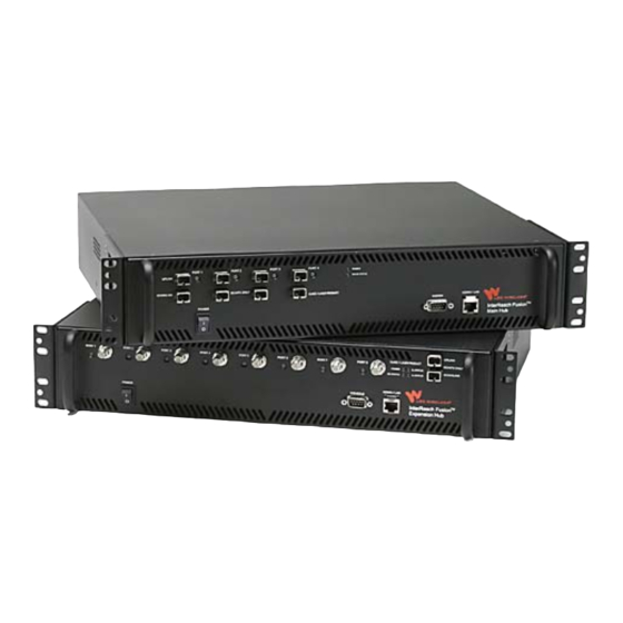
LGC wireless InterReach Fusion Installation, Operation And Reference Manual (210 pages)
Brand:
LGC wireless
| Category:
Receiver
| Size: 2 MB
Table of Contents
Table of Contents
5
Limited Warranty
4
General Information
15
Section 1 General Information
15
Firmware Release
16
Purpose and Scope
16
Section 1.1 Firmware Release
16
Section 1.2 Purpose and Scope
16
Conventions in this Manual
17
Section 1.3 Conventions in this Manual
17
Standards Conformance
18
Related Publications
18
Section 1.4 Standards Conformance
18
Section 1.5 Related Publications
18
System Description
19
Interreach Fusion System Description
19
System Overview
19
Section 2.1 System Overview
20
System Hardware Description
21
Section 2.2 System Hardware Description
21
System OA&M Capabilities Overview
22
Figure 2-1 Fusion System Hardware
22
Section 2.3 System OA&M Capabilities Overview
22
Figure 2-2 Three Methods for OA&M Communications
23
System Monitoring and Reporting
23
Figure 2-3 System Monitoring and Reporting
24
Using Alarm Contacts
24
System Connectivity
25
Figure 2-4 Fusion's Double Star Architecture
25
Section 2.4 System Connectivity
25
System Operation
26
Figure 2-5 Downlink (Base Station to Wireless Devices)
26
Figure 2-6 Uplink (Wireless Devices to Base Station)
26
Section 2.5 System Operation
26
System Specifications
27
Table 2-1 Physical Specifications
27
Section 2.6 System Specifications
27
RF End-To-End Performance
28
Table 2-2 Wavelength and Laser Power Specifications
28
Table 2-3 Environmental Specifications
28
Table 2-4 Operating Frequencies
28
Table 2-5 850 Mhz RF End-To-End Performance
29
Table 2-6 1900 Mhz RF End-To-End Performance
30
Table 2-7 900 Mhz RF End-To-End Performance
30
Table 2-8 1800 Mhz RF End-To-End Performance
30
Table 2-10 2100 Mhz RF End-To-End Performance
31
Table 2-11 800 Mhz (SMR) RF End-To-End Performance
31
Table 2-9 900 Mhz RF End-To-End Performance
31
Table 2-12 900 Mhz (SMR) RF End-To-End Performance
32
Table 2-13 1900 Mhz RF End-To-End Performance
32
Fusion Main Hub
33
SECTION 3 Fusion Main Hub
33
Fusion Main Hub
34
Figure 3-1 Main Hub in a Fusion System
34
Figure 3-2 Main Hub Block Diagram
35
Figure 3-3 Fusion Main Hub Front Panel
36
Fusion Main Hub Front Panel
36
Section 3.1 Fusion Main Hub Front Panel
36
Communications RS-232 Serial Connector
37
Hub LED Indicators
37
Optical Fiber Uplink/Downlink Ports
37
Table 3-1 Fusion Hub Status LED States
38
Table 3-2 Fusion Hub Port LED States
39
9-Pin D-Sub Connector
40
Figure 3-4 Fusion Main Hub Rear Panel
40
Fusion Main Hub Rear Panel
40
Fusion Main Hub Rear Panel Connectors
40
Section 3.2 Fusion Main Hub Rear Panel
40
N-Type Female Connectors
41
Table 3-3 9-Pin D-Sub Pin Connector Functions
41
Main Hub Specifications
42
Section 3.3 Main Hub Specifications
42
Description
43
Faults, Warnings, and Status Messages
43
Section 3.4 Faults, Warnings, and Status Messages
43
View Preference
44
Fusion Expansion Hub
47
Expansion Hub Overview
47
Figure 4-1 Expansion Hub in a Fusion System
47
Figure 4-2 Expansion Hub Block Diagram
48
Expansion Hub Front Panel
49
Figure 4-3 Expansion Hub Front Panel
49
Manufacturing RS-232 Serial Connector
50
Ohm Type F Connectors
50
Optical Fiber Uplink/Downlink Connectors
50
LED Indicators
51
Table 4-1 Expansion Hub Unit Status and DL/UL Status LED States
52
Table 4-2 Fusion Expansion Hub Port LED States
53
Expansion Hub Rear Panel
54
Figure 4-4 Expansion Hub Rear Panel
54
Table 4-3 9-Pin D-Sub Pin Connector Functions
54
Faults, Warnings, and Status Messages
55
Expansion Hub Specifications
56
Remote Access Unit
57
RAU Overview
57
Figure 5-1 Remote Access Unit in a Unison System
58
Figure 5-2 Remote Access Unit Block Diagram
58
Section 5.1 RAU Overview
59
Table 5-1 Frequency Bands Covered by Fusion Raus
59
Remote Access Unit Connectors
60
50 Ohm Type-N Connector
60
75 Ohm Type-F Connector
60
Section 5.2 Remote Access Unit Connectors
60
Faults and Warnings
61
RAU LED Indicators
61
Section 5.3 RAU LED Indicators
61
Section 5.4 Faults and Warnings
61
Status Leds
61
Table 5-3 Remote Access Unit LED States
61
Remote Access Unit Specifications
62
Section 5.5 Remote Access Unit Specifications
62
Designing a Fusion Solution
63
Overview
63
Section 6.1 Overview
64
Downlink RSSI Design Goal
65
Section 6.2 Downlink RSSI Design Goal
65
Maximum Output Power Per Carrier
66
Section 6.3 Maximum Output Power Per Carrier
66
850 Mhz Cellular
67
800 Mhz or 900 Mhz SMR
68
Table 6-1 Power Per Carrier
68
900 Mhz EGSM and EDGE
69
Table 6-2 GSM/EGSM and EDGE Power Per Carrier
69
1800 Mhz DCS
70
Table 6-3 DCS Power Per Carrier
70
1900 Mhz PCS
71
Table 6-4 PCS Power Per Carrier
71
Ghz UMTS
72
Table 6-5 UMTS Power Per Carrier
72
Section 6.4 System Gain
73
System Gain
73
System Gain (Loss) Relative to CATV Cable Type Length
73
Table 6-6 System Gain (Loss) Relative to CATV Cable Length
74
Estimating RF Coverage
75
Figure 6-1 Determining APL between the Antenna and the Wireless Device
75
Section 6.5 Estimating RF Coverage
75
Path Loss Equation
76
Table 6-8 Average Signal Loss of Common Building Materials
76
RAU Coverage Distance
77
Table 6-9 Frequency Bands and the Value of the First Term in Equation
77
Table 6-10 Estimated Path Loss Slope for Different In-Building Environments
78
Table 6-11 Approximate Radiated Distance from Antenna for 800 Mhz SMR Applications
79
Table 6-12 Approximate Radiated Distance from Antenna for 850 Mhz Cellular Applications
79
Table 6-13 Approximate Radiated Distance from Antenna for 900 Mhz GSM Applications
79
Table 6-14 Approximate Radiated Distance from Antenna for 900 Mhz EGSM Applications
80
Table 6-15 Approximate Radiated Distance from Antenna for 1800 Mhz DCS Applications
80
Table 6-16 Approximate Radiated Distance from Antenna for 1900 Mhz PCS Applications
81
Table 6-17 Approximate Radiated Distance from Antenna for 2.1 Ghz UMTS Applications
81
Examples of Design Estimates
82
Table 6-7 Coaxial Cable Losses (Lcoax)
75
Link Budget Analysis
86
Elements of a Link Budget for Narrowband Standards
86
Section 6.6 Link Budget Analysis
86
Narrowband Link Budget Analysis for a Microcell Application
89
Table 6-19 Narrowband Link Budget Analysis: Downlink
89
Table 6-20 Narrowband Link Budget Analysis: Uplink
90
Elements of a Link Budget for CDMA Standards
91
Table 6-21 Distribution of Power Within a CDMA Signal
91
Table 6-22 Additional Link Budget Considerations for CDMA
92
CDMA Link Budget Analysis for a Microcell Application
94
Table 6-23 CDMA Link Budget Analysis: Downlink
94
Table 6-24 CDMA Link Budget Analysis: Uplink
96
Considerations for Re-Radiation (Over-The-Air) Systems
97
Optical Power Budget
98
Section 6.7 Optical Power Budget
98
Connecting a Main Hub to a Base Station
99
Uplink Attenuation
99
Section 6.8 Connecting a Main Hub to a Base Station
99
RAU Attenuation and ALC
100
Figure 6-2 ALC Operation
101
Using the RAU 10 Db Attenuation Setting
101
Using the Uplink ALC Setting
102
Installing Fusion
103
Installation Requirements
103
Cable and Connector Requirements
104
Component Location Requirements
104
Distance Requirements
105
Safety Precautions
105
Installation Guidelines
105
Table 7-1 Distance Requirements
105
General Safety Precautions
106
Fiber Port Safety Precautions
107
Preparing for System Installation
108
Installation Checklist
108
Pre-Installation Inspection
108
Table 7-2 Installation Checklist
108
Table 7-3 Tools and Materials Required for Component Installation
110
Tools and Materials Required
110
Optional Accessories
111
Table 7-4 Optional Accessories for Component Installation
111
7.4 Fusion Installation Procedures
112
Fusion Installation Procedures
112
Installing a Fusion Main Hub
113
Installing a Fusion Main Hub in a Rack
113
Using the Rack-Mounting Option
113
Installing a Main Hub Using the 12" Wall-Mounted Rack (PN 4712)
114
Installing an Optional Cable Manager in the Rack
114
Figure 7-2 Installing in the Recessed Mounting Position
115
Installing a Fusion Main Hub Directly to the Wall
115
Powering on the Main Hub
119
Table 7-5 Troubleshooting Main Hub Leds During Installation
119
Installing an Expansion Hub in a Rack
121
Installing Expansion Hubs
121
Installing an Expansion Hub Using the 12" Wall-Mounted Rack
122
Connecting the Fiber Cables to the Expansion Hub
123
Installing an Optional Cable Manager in the Rack
123
Powering on the Expansion Hub
123
Connecting the 75 Ohm CATV Cables
124
Troubleshooting Expansion Hub Leds During Installation
125
Table 7-6 Troubleshooting Expansion Hub Leds During Installation
126
Installing Passive Antennas
127
Installing Raus
127
Figure 7-5 800/850 Mhz Spectrum
128
Figure 7-6 Guideline for Unison RAU Antenna Placement
128
Connecting the Antenna to the RAU
129
Connecting the CATV Cable
129
Table 7-7 Troubleshooting RAU Leds During Installation
130
Troubleshooting Using RAU Leds During Installation
130
Configuring the System
131
Connecting the PC to the Fusion Main Hub to Run Adminbrowser
131
Installing Raus in a Multiple Operator System
131
Figure 7-7 Internet Protocol (TCP/IP) Properties Window
132
Programming the Fusion Main Hub Using Adminbrowser
132
Figure 7-8 Local Area Connection Properties Window
133
Figure 7-10 Adminbrowser Configuration Window
134
Figure 7-9 Set Time and Date Window
134
Figure 7-11 Adminbrowser Configuration Window (Continued)
135
Splicing Fiber Optic Cable
137
Fusion Splices
137
Interfacing the Fusion Main Hub to an RF Source
139
Connecting a Single Fusion Main Hub to an RF Source
139
Figure 7-12 Simplex Base Station to a Fusion Main Hub
140
Figure 7-13 Duplex Base Station to a Fusion Main Hub
141
Figure 7-14 Connecting a Fusion Main Hub to Multiple Base Stations
142
Figure 7-15 Connecting a Fusion Main Hub to a Roof-Top Antenna
143
Connecting Multiple Fusion Main Hubs to an RF Source
144
Figure 7-16 Connecting Two Fusion Main Hub's RF Band Ports to a Simplex Repeater or Base Station
146
Figure 7-17 Connecting Two Fusion Main Hub's RF Band Ports to a Duplex Repeater or Base Station
148
Connecting Contact Alarms to a Fusion System
149
Table 7-8 Alarm Types
149
Alarm Source
150
Figure 7-18 Connecting Metroreach to Fusion
150
Figure 7-19 Using a BTS to Monitor Fusion
151
Figure 7-20 Using a BTS and Adminbrowser to Monitor Fusion
152
Alarm Sense
153
Figure 7-21 Using Fusion to Monitor Unison
153
Figure 7-22 Alarm Sense Contacts
154
Alarm Cables
155
Figure 7-23 5-Port Alarm Daisy-Chain Cable
155
Alarm Monitoring Connectivity Options
157
Direct Connection
157
Figure 7-25 OA&M Direct Connection
157
Modem Connection
158
100 BASE-T Port Expander Connection
159
Figure 7-28 OA&M Connection Using a POTS Line Sharing Switch
160
POTS Line Sharing Switch Connection
160
Figure 7-29 Cascading Line Sharing Switches
161
Ethernet LAN Connection
162
Figure 7-31 Fusion SNMP Configuration Options
163
SNMP Interface
163
Replacing Fusion Components
165
Replacing an RAU
165
Replacing a Fusion Expansion Hub
167
Replacing a Fusion Main Hub
168
Maintenance, Troubleshooting, and Technical Assistance
171
Service
171
Maintenance
172
Troubleshooting
173
Troubleshooting Recommendations
174
Troubleshooting Using Adminbrowser
174
Fault/Warning/Status Indications
175
Troubleshooting Using Leds
176
Table 9-1 Troubleshooting Main Hub Port Leds During Normal Operation
177
Table 9-2 Troubleshooting Main Hub Status Leds During Normal Operation
178
Table 9-3 Troubleshooting Expansion Hub Port Leds During Normal Operation
179
Table 9-4 Troubleshooting Expansion Hub Status Leds During Normal Operation
180
Troubleshooting CATV
181
Technical Assistance
181
Table 9-5 Summary of CATV Cable Wiring Problems
181
APPENDIX A Cables and Connectors
183
75 Ohm CATV Cable
183
Figure A-1 Commscope 2065V for
184
Figure A-2 Commscope 2279V for
185
Figure A-3 Commscope 2293K for
186
Fiber Optical Cables
189
Coaxial Cable
189
Standard Modem Cable
190
Figure A-1 Standard Modem Cable Pinout
190
TCP/IP Cross-Over Cable
191
Figure A-2 Wiring Map for TCP/IP Cable
191
DB-25 to DB-9 Null Modem Cable
192
APPENDIX B Compliance
193
Fusion System Approval Status
193
Human Exposure to RF
195
APPENDIX C Faults, Warnings, Status Tables
197
Fault Messages Reported by Hubs
197
Faults Reported for System CPU
201
Table C-2 Faults for System CPU
201
Section C.2 Faults Reported for System CPU
201
This Appendix Contains the Following Sections:
201
Faults for Raus
202
Table C-3 Faults for Raus
202
Section C.3 Faults for Raus
202
Section C.4 Warning/Status Messages for Hubs
203
Warning/Status Messages for Hubs
203
Table C-4 Warnings/Status Messages for Hubs
204
Warning/Status Messages for System Cpus
208
Table C-5 Warning/Status Messages for System Cpus
208
Section C.5 Warning/Status Messages for System Cpus
208
Warning /Status Messages for Raus
209
Table C-6 Warning/Status Messages for Raus
209
Section C.6 Warning /Status Messages for Raus
209
Interreach Fusion Installation, Operation, and Reference Manual
210
D-620TBD-0-20 Rev a
210
Faults, Warnings, Status Tables
197
Advertisement
Advertisement
Related Products
LGC Wireless InterReach Fusion SingleStar
LGC Wireless InterReach Unison
LGC wireless Categories
Switch
Network Hardware
Receiver
More LGC wireless Manuals
Login
Sign In
OR
Sign in with Facebook
Sign in with Google
Upload manual
Upload from disk
Upload from URL