
Summary of Contents for LGC wireless InterReach Fusion
- Page 1 ® InterReach Fusion Installation, Operation, and Reference Manual D-620TBD-0-20 Rev A...
- Page 2 Help Hot Line (U.S. only): 1-800-530-9960 D-620TBD-0-20 CONFIDENTIAL Rev A...
- Page 3 This manual is produced for use by LGC Wireless personnel, licensees, and customers. The information contained herein is the property of LGC Wireless. No part of this document may be reproduced or transmitted in any form or by any means, electronic or mechanical, for any purpose, without the express written permission of LGC Wireless.
-
Page 4: Limited Warranty
Licensed Operators LGC Wireless’ equipment is designed to operate in the licensed frequency bands of mobile, cellular, and PCS operators. In the USA, the EU, and most countries this equipment may only be used by the licensee, his authorized agents or those with written authorization to do so. -
Page 5: Table Of Contents
........3-11 InterReach Fusion Installation, Operation, and Reference Manual... - Page 6 6.6.3 Elements of a Link Budget for CDMA Standards ..6-29 6.6.4 CDMA Link Budget Analysis for a Microcell Application . 6-32 InterReach Fusion Installation, Operation, and Reference Manual D-620TBD-0-20 Rev A...
- Page 7 ........7-61 InterReach Fusion Installation, Operation, and Reference Manual...
- Page 8 ... . C-12 C.6 Warning /Status Messages for RAUs ....C-13 InterReach Fusion Installation, Operation, and Reference Manual D-620TBD-0-20 Rev A...
- Page 9 ....... . . 7-32 InterReach Fusion Installation, Operation, and Reference Manual...
- Page 10 ....... . A-9 Figure A-3 DB-9 Female to DB-9 Female Null Modem Cable Diagram ..A-10 InterReach Fusion Installation, Operation, and Reference Manual D-620TBD-0-20 Rev A...
- Page 11 ........6-9 InterReach Fusion Installation, Operation, and Reference Manual...
- Page 12 Troubleshooting Main Hub Status LEDs During Normal Operation . . 9-8 Table 9-3 Troubleshooting Expansion Hub Port LEDs During Normal Operation 9-9 Table 9-4 Troubleshooting Expansion Hub Status LEDs During Normal Operation 9-10 InterReach Fusion Installation, Operation, and Reference Manual D-620TBD-0-20 Rev D...
- Page 13 Warning/Status Messages for RAUs ......C-13 InterReach Fusion Installation, Operation, and Reference Manual D-620TBD-0-20 Rev D...
- Page 14 CONFIDENTIAL InterReach Fusion Installation, Operation, and Reference Manual D-620TBD-0-20 Rev D...
-
Page 15: General Information
• Section 1.5 Related Publications ........1-4 InterReach Fusion Installation, Operation, and Reference Manual... -
Page 16: Firmware Release
For the latest Software and Firmware Release and associated documentation, access the LGC Wireless Customer Portal at lgcwireless.com. Purpose and Scope This document describes the InterReach Fusion system. • Section 2 InterReach Fusion System Description This section provides an overview of the Fusion hardware and OA&M capabilities. -
Page 17: Conventions In This Manual
Conventions in this Manual • Appendix A Cables and Connectors This appendix provides connector and cable descriptions and requirements. It also includes cable strapping, connector crimping tools, and diagrams. • Appendix B Compliance This section lists safety and radio/EMC approvals. Conventions in this Manual The following table lists the type style conventions used in this manual. -
Page 18: Standards Conformance
• Fusion uses the TIA-570-B cabling standards for ease of installation. • Refer to Appendix B for compliance information. Related Publications • AdminBrowser User Manual, LGC Wireless part number D-620607-0-20 Rev. A • MetroReach Focus Configuration, Installation, and Reference Manual; LGC Wireless part number 8500-10 •... -
Page 19: Interreach Fusion System Description
• Section 2.6 System Specifications ....... . . 2-9 System Overview InterReach Fusion is an intelligent fiber optics/CATV, multi-band (frequencies) wire- less networking system designed to handle both wireless voice and data communica- tions over licensed frequencies. -
Page 20: Section 2.1 System Overview
– Uplink level control protects the system from input overload and can be optimized for either a single operator or multiple operators/protocols. – VSWR check on RAU reports if there is a disconnected antenna. InterReach Fusion Installation, Operation, and Reference Manual CONFIDENTIAL D-620TBD-0-20 Rev A... -
Page 21: System Hardware Description
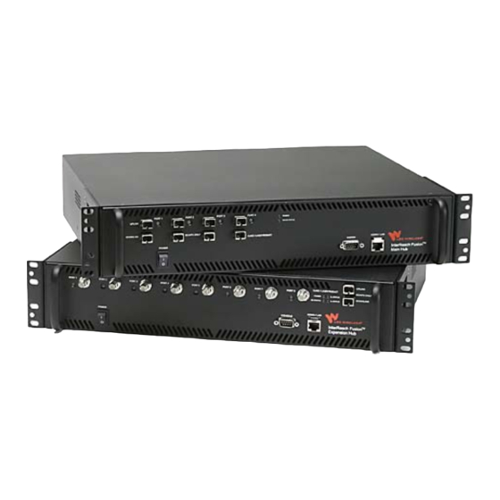
OA&M software package. System Hardware Description The InterReach Fusion system consists of three modular components: • 19" rack-mountable Main Hub (connects to up to 4 Expansion Hubs) • Converts RF signals to optical IF on the downlink; optical IF-to-RF on the uplink •... -
Page 22: System Oa&M Capabilities Overview
Fusion System Hardware Figure 2-1 System OA&M Capabilities Overview InterReach Fusion is microprocessor controlled and contains firmware to enable much of the operations, administration, and maintenance (OA&M) functionality. Complete alarming, down to the field replaceable unit (that is, Fusion Main Hub, Expansion Hub, and Remote Access Unit) and the cabling infrastructure, is available. -
Page 23: System Monitoring And Reporting
System OA&M Capabilities Overview Three Methods for OA&M Communications Figure 2-2 Use AdminBrowser to configure PC/Laptop Modem RS-232 or monitor a local or a remote running a Fusion system. Standard Browser PSTN RS-232 Ethernet TCP/IP Switch Ethernet Fusion Main Hub R-J-45 Modem Ethernet... -
Page 24: Using Alarm Contacts
When you connect MetroReach Focus or a BTS to the Fusion, the Fusion Main Hub outputs the alarms (alarm source) and MetroReach Focus or the BTS receives the alarms (alarm sense). This is described in Section 7.7.1 on page 7-48. InterReach Fusion Installation, Operation, and Reference Manual CONFIDENTIAL D-620TBD-0-20 Rev A... -
Page 25: System Connectivity
System Connectivity System Connectivity The double star architecture of the Fusion system, illustrated in Figure 2-4, provides excellent system scalability and reliability. The system requires only one pair of fibers for eight antenna points. This makes any system expansion, such as adding an extra antenna for additional coverage, potentially as easy as pulling an extra CATV cable. -
Page 26: System Operation
The Main Hub sends to four) using optical uplink RF signals to a fiber cable and con- base station using verts them to RF sig- 50 Ohm coaxial cable. nals. InterReach Fusion Installation, Operation, and Reference Manual CONFIDENTIAL D-620TBD-0-20 Rev A... -
Page 27: System Specifications
System Specifications System Specifications Physical Specifications Table 2-1 Parameter Main Hub Expansion Hub Remote Access Unit IF/RF Connectors 6-type “N”, female (50 Ohm), 8-type “F”, female (CATV One F, female (CATV -75 1 Downlink/Uplink pair per band 75 Ohm) Ohm) One N, female (coaxial - 50 Ohm) External Alarm Connector... -
Page 28: Rf End-To-End Performance
NOTE: The system gain is adjustable in 1 dB steps from 0 to 15 dB, and the gain of each RAU can be attenuated up to 10 dB in 1dB steps. 2-10 InterReach Fusion Installation, Operation, and Reference Manual CONFIDENTIAL D-620TBD-0-20 Rev A... -
Page 29: Table 2-5 850 Mhz Rf End-To-End Performance
System Specifications 850/1900 RAU 850 MHz RF End-to-End Performance Table 2-5 Typical Parameter Downlink Uplink Average gain with 75 m RG-59 at 25°C (77°F) (dB) Ripple with 150 m RG-59 (dB) Output IP3 (dBm) Input IP3 (dBm) –5 Output 1 dB Compression Point (dBm) Noise Figure 1 Hub-8 RAUs (dB) Help Hot Line (U.S. -
Page 30: Table 2-6 1900 Mhz Rf End-To-End Performance
Uplink gain roll off with 75 m RG-59 (dB)* Output IP3 (dBm) Input IP3 (dBm) –5 Output 1 dB Compression Point (dBm) Noise Figure 1 Hub-8 RAUs (dB) *Outside the center 60 MHz 2-12 InterReach Fusion Installation, Operation, and Reference Manual CONFIDENTIAL D-620TBD-0-20 Rev A... -
Page 31: Table 2-9 900 Mhz Rf End-To-End Performance
System Specifications 900/2100 RAU 900 MHz RF End-to-End Performance Table 2-9 Typical Parameter Downlink Uplink Average Downlink gain with 75 m RG-59 at 25°C (77°F) (dB) Ripple with 75 m RG-59 (dB) Output IP3 (dBm) Input IP3 (dBm) –5 Output 1 dB Compression Point (dBm) Noise Figure 1 Hub-8 RAUs (dB) 2100 MHz RF End-to-End Performance Table 2-10... -
Page 32: Table 2-12 900 Mhz (Smr) Rf End-To-End Performance
Ripple with 150 m CATV (dB) Output IP3 (dBm) Input IP3 (dBm) –5 Output 1 dB Compression Point (dBm) Noise Figure 1 MH-1 EH-8 RAUs (dB) Noise Figure 1 MH-4 EH-32 RAUs (dB) 2-14 InterReach Fusion Installation, Operation, and Reference Manual CONFIDENTIAL D-620TBD-0-20 Rev A... -
Page 33: Section 3 Fusion Main Hub
RF3) goes to a 6 MHz sub-band of Band 1 and is functional only with the FSN-F0901900 RAU. The system installs in a 19" equipment rack and is usually co-located with the RF source in a telecommunications closet. InterReach Fusion Installation, Operation, and Reference Manual CONFIDENTIAL D-620TBD-0-20 Rev A... -
Page 34: Fusion Main Hub
The Main Hub also receives status information from the Expansion Hubs and all RAUs using the fiber optic cable. Figure 3-2 shows a detailed view of the major RF and optical functional blocks of the Main Hub. InterReach Fusion Installation, Operation, and Reference Manual CONFIDENTIAL D-620TBD-0-20 Rev A... -
Page 35: Figure 3-2 Main Hub Block Diagram
Main Hub Block Diagram Figure 3-2 Help Hot Line (U.S. only): 1-800-530-9960 CONFIDENTIAL D-620TBD-0-20 Rev A... -
Page 36: Fusion Main Hub Front Panel
(labeled MODEM One RJ-45 female connector for system communication and diagnostics using a PC/laptop with direct connect or using a LAN switch (labeled ADMIN/LAN Power switch InterReach Fusion Installation, Operation, and Reference Manual CONFIDENTIAL D-620TBD-0-20 Rev A... -
Page 37: Optical Fiber Uplink/Downlink Ports
Fusion Main Hub Front Panel 3.1.1 Optical Fiber Uplink/Downlink Ports The optical fiber uplink/downlink ports transmit and receive optical signals between the Main Hub and up to four Expansion Hubs using industry-standard SMF or MMF cable. There are four fiber ports on the front panel of the Main Hub; one port per Expansion Hub. -
Page 38: Table 3-1 Fusion Hub Status Led States
• The Main Hub is connected to power and all power supplies are operating. POWER STATUS Use AdminBrowser to power status. • The Main Hub is reporting a fault or lockout condition. InterReach Fusion Installation, Operation, and Reference Manual CONFIDENTIAL D-620TBD-0-20 Rev A... -
Page 39: Table 3-2 Fusion Hub Port Led States
Fusion Main Hub Front Panel Fusion Hub Status LED States (continued) Table 3-1 LED State Indicates Green • The Main Hub is connected to power and all power supplies are operating. POWER STATUS • The Main Hub DL input signal level is too high. (60-ppm) •... -
Page 40: Fusion Main Hub Rear Panel
The 9-pin D-sub connector (labeled ) provides a contact alarm for fault DIAGNOSTIC 1 and warning system alarm monitoring. Table 3-3 lists the function of each pin on the 9-pin D-sub connector. InterReach Fusion Installation, Operation, and Reference Manual CONFIDENTIAL D-620TBD-0-20 Rev A... -
Page 41: N-Type Female Connectors
Fusion Main Hub Rear Panel 9-pin D-sub Pin Connector Functions Table 3-3 Function Alarm Sense Input (DC Ground) Alarm Sense Input 3 Alarm Sense Input 2 Warning Source Contact (positive connection) Warning Contact (negative connection) DC Ground (common) Fault Source Contact (positive connection) Alarm Sense Input 1 Fault Source Contact (negative connection) This interface can both generate two source contact alarms (Fault and Warning) and... -
Page 42: Main Hub Specifications
Excluding angle brackets for the 19” rack mounting of the Hub. b. It is critical to system performance that only SC/APC fiber connectors are used throughout the fiber network, including fiber distribution panels. 3-10 InterReach Fusion Installation, Operation, and Reference Manual CONFIDENTIAL D-620TBD-0-20 Rev A... -
Page 43: Faults, Warnings, And Status Messages
Faults, Warnings, and Status Messages Faults, Warnings, and Status Messages 3.4.1 Description The Fusion Main Hub monitors and reports changes or events in system performance • Ensure that fiber receivers, amplifiers and IF/RF paths are functioning properly. • Ensure that Expansion Hubs and Remote Access Units are connected and function- ing properly. -
Page 44: View Preference
The only exception to when the event filtering is ignored is during the Install/Config- ure command. All events are displayed regardless of the event filtering setting. This ensures a smooth installation. 3-12 InterReach Fusion Installation, Operation, and Reference Manual CONFIDENTIAL D-620TBD-0-20 Rev A... - Page 45 Faults, Warnings, and Status Messages This page is intentionally left blank. Help Hot Line (U.S. only): 1-800-530-9960 3-13 CONFIDENTIAL D-620TBD-0-20 Rev A...
- Page 46 Faults, Warnings, and Status Messages 3-14 InterReach Fusion Installation, Operation, and Reference Manual CONFIDENTIAL D-620TBD-0-20 Rev A...
-
Page 47: Fusion Expansion Hub
Main Hub using fiber optic cable. The Expansion Hub also receives RAU status information using CATV cable and sends it and its own status information to the Main Hub using the fiber optic cable. InterReach Fusion Installation, Operation, and Reference Manual CONFIDENTIAL D-620TBD-0-20 Rev H... -
Page 48: Figure 4-2 Expansion Hub Block Diagram
Expansion Hub Overview Expansion Hub Block Diagram Figure 4-2 InterReach Fusion Installation, Operation, and Reference Manual CONFIDENTIAL D-620TBD-0-20 Rev H... -
Page 49: Expansion Hub Front Panel
Expansion Hub Front Panel Expansion Hub Front Panel Expansion Hub Front Panel Figure 4-3 One port LED per type F connector port for link status and downstream RAY sta- tus (8 pair total). Eight CATV cable, type F connectors (labeled PORT 1 One pair of unit status LEDs •... -
Page 50: Ohm Type F Connectors
Refer to Appendix A for approved cables and connectors. 4.2.2 Manufacturing RS-232 Serial Connector Console Port This console port is only used by LGC Wireless manufacturing test purposes. DO NOT USE IT. Local Monitoring Use a crossover Ethernet cable (PN-4069-ADB) to connect a laptop or PC to the RJ-45 female connector for local monitoring or configuring the Expansion Hub and associated RAUs using the AdminBrowser-EH resident software. -
Page 51: Led Indicators
Expansion Hub Front Panel SC/APC fiber connectors throughout the fiber network, including fiber distribu- tion panels. This is critical for ensuring system performance. 4.2.4 LED Indicators The unit’s front panel LEDs indicate fault conditions and commanded or fault lockouts. The LEDs do not indicate warnings or whether the system test has been performed. Only use the LEDs to provide basic information or as a backup when you are not using AdminBrowser. -
Page 52: Table 4-1 Expansion Hub Unit Status And Dl/Ul Status Led States
90 seconds after power on. If initially green, then red after 90 seconds, it means that there is no communication with the Main Hub. If red on power up, replace the Expansion Hub. InterReach Fusion Installation, Operation, and Reference Manual CONFIDENTIAL D-620TBD-0-20 Rev H... -
Page 53: Table 4-2 Fusion Expansion Hub Port Led States
Expansion Hub Front Panel Expansion Hub Unit Status and DL/UL Status LED States (continued) Table 4-1 LED State Indicates Green / Red • Optical power in is below minimum (the Main Hub is not connected, POWER DL STATUS is not powered, or the Main Hub’s downlink laser has failed, or the EH STATUS UL STATUS Red / Red... -
Page 54: Expansion Hub Rear Panel
Alarm Sense Input 3 Alarm Sense Input 2 DC Ground (common) Alarm Sense Input 1 This interface can monitor and generate three single external alarm contacts (Alarm Sense Input 1 through 3). InterReach Fusion Installation, Operation, and Reference Manual CONFIDENTIAL D-620TBD-0-20 Rev H... -
Page 55: Faults, Warnings, And Status Messages
Faults, Warnings, and Status Messages Faults, Warnings, and Status Messages This interface monitors the output contact closures from a Universal Power Supply (UPS). Verify the output contact closure state (normally closed or normally open) of the UPS, and set the appropriate contact definition using AdminBrowser. •... -
Page 56: Expansion Hub Specifications
It is critical to system performance that only SC/APC fiber connectors are used throughout the fiber network, including fiber distribution panels. c. For Japan, see separate addendum - Japan Specification Document. 4-10 InterReach Fusion Installation, Operation, and Reference Manual CONFIDENTIAL D-620TBD-0-20 Rev H... -
Page 57: Remote Access Unit
RAU. An RAU passes RF signals between an Expansion Hub and an attached passive antenna where the signals are transmitted to wireless devices as shown in Figure 5-1. InterReach Fusion Installation, Operation, and Reference Manual CONFIDENTIAL D-620TBD-0-20 Rev A... -
Page 58: Figure 5-1 Remote Access Unit In A Unison System
Fusion Hub using CATV cable. The RAU receives 54VDC power from the Fusion Hub port through the 75 Ohm CATV cable center pin. Remote Access Unit Block Diagram Figure 5-2 InterReach Fusion Installation, Operation, and Reference Manual CONFIDENTIAL D-620TBD-0-20 Rev A... -
Page 59: Table 5-1 Frequency Bands Covered By Fusion Raus
RAU Overview The Fusion RAUs are manufactured to a specific set of bands (one 35 MHz-Band 1, one 75 MHz-Band 2). Table 5-1 lists the Fusion RAUs, the Fusion Band, and the fre- quency bands they cover. Frequency Bands Covered by Fusion RAUs Table 5-1 RF Passband Fusion... -
Page 60: Remote Access Unit Connectors
NOTE: For system performance, it is important that you use only low loss, solid copper center conductor CATV cable with quality F connectors that use captive centerpin conductors. Refer to Appendix A for specific information. InterReach Fusion Installation, Operation, and Reference Manual CONFIDENTIAL D-620TBD-0-20 Rev A... -
Page 61: Rau Led Indicators
RAU LED Indicators RAU LED Indicators Upon power up, the RAU goes through a two-second test to check the LED lamps. During this time, the LEDs blink green/green red/red, letting you visually verify that the LED lamps and the firmware are functioning properly. NOTE: Refer to Section 9 for troubleshooting using the LEDs. -
Page 62: Remote Access Unit Specifications
NOTE: For system performance, it is important that you use only low loss, solid copper center conductor CATV cable with quality F connectors that use captive centerpin conductors. Refer to Appendix A for more information. InterReach Fusion Installation, Operation, and Reference Manual CONFIDENTIAL D-620TBD-0-20 Rev A... -
Page 63: Designing A Fusion Solution
• Number of sectors and peak capacity per sector (translates to the number of RF carriers that the system will have to transmit) • Downlink RSSI design goal (RSSI, received signal strength at the wireless handset, for example, –85 dBm) InterReach Fusion Installation, Operation, and Reference Manual CONFIDENTIAL D-6206TBD-0-20 Rev A... -
Page 64: Section 6.1 Overview
RF site-survey of the building. This involves transmitting a calibrated tone for a fixed antenna and making measurements with a mobile antenna throughout the area surrounding the transmitter. InterReach Fusion Installation, Operation, and Reference Manual CONFIDENTIAL D-6206TBD-0-20 Rev A... -
Page 65: Downlink Rssi Design Goal
The individual elements that must be considered in designing a Fusion solution are explained in the following sections. NOTE: Access the LGC Wireless Customer Portal at LGCWireless.com for on-line dimensioning and design tools. Downlink RSSI Design Goal Wireless service providers typically provide a minimum downlink signal level and an associated confidence factor when specifying coverage requirements. -
Page 66: Maximum Output Power Per Carrier
Hub. Do not exceed the maximum composite input power of 1W (+30 dBm) to the Hub at any time. NOTE: These specifications are for downlink power at the RAU output (excluding antenna). InterReach Fusion Installation, Operation, and Reference Manual CONFIDENTIAL D-6206TBD-0-20 Rev A... -
Page 67: 850 Mhz Cellular
Maximum Output Power per Carrier 6.3.1 850 MHz Cellular Cellular Power per Carrier Power per Carrier (dBm) No. of Carriers AMPS TDMA EDGE CDMA WCDMA 16.5 16.5 16.5 16.5 16.5 16.5 13.5 13.5 16.5 15.0 11.5 11.5 13.5 10.0 10.0 10.0 12.0 11.5... -
Page 68: 800 Mhz Or 900 Mhz Smr
10.0 10.5 10.5 10.5 Note: Operation at or above these output power levels may prevent Fusion from meeting RF performance specifications or FCC Part 15 and EN55022 emissions requirements. InterReach Fusion Installation, Operation, and Reference Manual CONFIDENTIAL D-6206TBD-0-20 Rev A... -
Page 69: 900 Mhz Egsm And Edge
Maximum Output Power per Carrier 6.3.3 900 MHz EGSM and EDGE GSM/EGSM and EDGE Power per Carrier Table 6-2 Power per Carrier (dBm) No. of Carriers EDGE 16.0 16.0 13.0 13.0 11.0 11.0 10.0 10.0 Note: Operation at or above these output power levels may prevent Fusion from meeting RF performance specifications or FCC Part 15 and EN55022 emissions requirements. -
Page 70: 1800 Mhz Dcs
11.5 10.5 10.5 Note: Operation at or above these output power levels may pre- vent Fusion from meeting RF performance specifications or FCC Part 15 and EN55022 emissions requirements. InterReach Fusion Installation, Operation, and Reference Manual CONFIDENTIAL D-6206TBD-0-20 Rev A... -
Page 71: 1900 Mhz Pcs
Maximum Output Power per Carrier 6.3.5 1900 MHz PCS PCS Power per Carrier Table 6-4 Power per Carrier (dBm) No. of Carriers TDMA EDGE CDMA WCDMA 16.5 16.5 16.5 16.0 15.0 16.5 15.5 15.5 13.0 11.0 15.0 13.5 13.5 11.0 13.0 12.0 12.0... -
Page 72: Ghz Umts
Design the initial coverage for two RF carriers, but reserve RAU ports on the Hub for future use. These ports can be used to fill potential coverage holes once the power per carrier is lowered to accommodate the two additional carriers. 6-10 InterReach Fusion Installation, Operation, and Reference Manual CONFIDENTIAL D-6206TBD-0-20 Rev A... -
Page 73: System Gain
System Gain System Gain The system gain of the Fusion defaults to 0 dB or can be set up to 15 dB in 1 dB increments. In addition, uplink and downlink gains of each RAU can be indepen- dently decreased by 10 dB in one dB steps using AdminBrowser. 6.4.1 System Gain (Loss) Relative to CATV Cable Type Length The recommended maximum lengths of CATV cable are as follows:... -
Page 74: Table 6-6 System Gain (Loss) Relative To Catv Cable Length
If the distance of a cable run is at its maximum and is of concern, LGC recommends the use of solid copper cable to ensure successful opera- tion. 6-12 InterReach Fusion Installation, Operation, and Reference Manual CONFIDENTIAL D-6206TBD-0-20 Rev A... -
Page 75: Estimating Rf Coverage
Estimating RF Coverage Estimating RF Coverage The maximum output power per carrier (based on the number and type of RF carriers being transmitted) and the minimum acceptable received power at the wireless device (that is, the RSSI design goal) essentially establish the RF downlink budget and, con- sequently, the maximum allowable path loss (APL) between the RAU’s antenna and the wireless device. -
Page 76: Path Loss Equation
Heavy machinery 1300 Equipment racks 1300 Assembly line 1300 Ceiling duct 1300 Metal stairs 1300 1. Rappaport, Theodore S. Wireless Communications, Principles, and Practice. Prentice Hall PTR, 1996. 6-14 InterReach Fusion Installation, Operation, and Reference Manual CONFIDENTIAL D-6206TBD-0-20 Rev A... -
Page 77: Rau Coverage Distance
Estimating RF Coverage 6.5.2 RAU Coverage Distance Use equations (1) and (2), on pages 6-13 and 6-14, respectively, to estimate the dis- tance from the antenna to where the RF signal decreases to the minimum acceptable level at the wireless device. With d set to one meter and path loss slope (PLS) defined as 10n, Equation (2) can be simplified to:... -
Page 78: Table 6-10 Estimated Path Loss Slope For Different In-Building Environments
• 6 dBm output per carrier at the RAU output • 3 dBi antenna gain • RSSI design goal = –85 dBm (typical for narrowband protocols, but not for spread-spectrum protocols) 6-16 InterReach Fusion Installation, Operation, and Reference Manual CONFIDENTIAL D-6206TBD-0-20 Rev A... -
Page 79: Table 6-11 Approximate Radiated Distance From Antenna For 800 Mhz Smr Applications
Estimating RF Coverage Approximate Radiated Distance from Antenna Table 6-11 for 800 MHz SMR Applications Distance from Antenna Environment Type Meters Feet Open Environment Moderately Open Environment Mildly Dense Environment Moderately Dense Environment Dense Environment Approximate Radiated Distance from Antenna Table 6-12 for 850 MHz Cellular Applications Distance from Antenna... -
Page 80: Table 6-14 Approximate Radiated Distance From Antenna For 900 Mhz Egsm Applications
Approximate Radiated Distance from Antenna Table 6-15 for 1800 MHz DCS Applications Distance from Antenna Facility Meters Feet Open Environment Moderately Open Environment Mildly Dense Environment Moderately Dense Environment Dense Environment 6-18 InterReach Fusion Installation, Operation, and Reference Manual CONFIDENTIAL D-6206TBD-0-20 Rev A... -
Page 81: Table 6-16 Approximate Radiated Distance From Antenna For 1900 Mhz Pcs Applications
Estimating RF Coverage Approximate Radiated Distance from Antenna Table 6-16 for 1900 MHz PCS Applications Distance from Antenna Facility Meters Feet Open Environment Moderately Open Environment Mildly Dense Environment Moderately Dense Environment Dense Environment Approximate Radiated Distance from Antenna Table 6-17 for 2.1 GHz UMTS Applications Distance from Antenna Facility... -
Page 82: Examples Of Design Estimates
For this case we assumed a circular radiation pattern, though the actual area covered depends upon the pattern of the antenna and the obstructions in the facility. 6-20 InterReach Fusion Installation, Operation, and Reference Manual CONFIDENTIAL D-6206TBD-0-20 Rev A... - Page 83 Estimating RF Coverage Equipment Required: Since you know the building size, you can now estimate the Fusion equipment quantities that will be needed. Before any RF levels are tested in the building, you can estimate that two antennas per level will be needed. This assumes no propagation between floors.
- Page 84 For this case we assumed a circular radiation pattern, though the actual area covered depends upon the pattern of the antenna and the obstructions in the facility. 6-22 InterReach Fusion Installation, Operation, and Reference Manual CONFIDENTIAL D-6206TBD-0-20 Rev A...
- Page 85 Estimating RF Coverage Equipment Required: Since you know the building size, you can now estimate the Fusion equipment quantities needed. Before you test any RF levels in the building, you can estimate that four antennas per level will be needed. This assumes no propagation between floors.
-
Page 86: Link Budget Analysis
Main Hub. WARNING: Exceeding the maximum input power of 1W (+30 dBm) could cause permanent damage to the Main Hub. NOTE: Visit the LGC Wireless customer portal at LGCWireless.com for the on-line Link Budget Tool. 6.6.1... - Page 87 Link Budget Analysis Link Budget Considerations for Narrowband Systems Table 6-18 Consideration Description BTS Transmit Power The power per carrier transmitted from the base station output Attenuation between This includes all losses: cable, attenuator, splitter/combiner, and so forth. BTS and Fusion On the downlink, attenuation must be chosen so that the maximum power per carrier going into the Main Hub does not exceed the levels given in Section 6.3.
- Page 88 This is also referred to as the “design goal”. The link budget says that you can achieve adequate cov- Signal Level erage if the signal level is, on average, above this level over 95% of the area covered, for example. 6-26 InterReach Fusion Installation, Operation, and Reference Manual CONFIDENTIAL D-6206TBD-0-20 Rev A...
-
Page 89: Narrowband Link Budget Analysis For A Microcell Application
Link Budget Analysis 6.6.2 Narrowband Link Budget Analysis for a Microcell Application Narrowband Link Budget Analysis: Downlink Table 6-19 Line Downlink Transmitter BTS transmit power per carrier (dBm) Attenuation between BTS and Fusion (dB) –23 Power into Fusion (dBm) Fusion gain (dB) Antenna gain (dBi) Radiated power per carrier (dBm) Airlink... -
Page 90: Table 6-20 Narrowband Link Budget Analysis: Uplink
• m = j + k + l • p = n – m – i Therefore, the system is downlink limited but the downlink and uplink are almost balanced, which is a desirable condition. 6-28 InterReach Fusion Installation, Operation, and Reference Manual CONFIDENTIAL D-6206TBD-0-20 Rev A... -
Page 91: Elements Of A Link Budget For Cdma Standards
Link Budget Analysis 6.6.3 Elements of a Link Budget for CDMA Standards A CDMA link budget is slightly more complicated because you must consider the spread spectrum nature of CDMA. Unlike narrowband standards such as TDMA and GSM, CDMA signals are spread over a relatively wide frequency band. Upon recep- tion, the CDMA signal is de-spread. -
Page 92: Table 6-22 Additional Link Budget Considerations For Cdma
(1.25 MHz / 14.4 Kbps) = 19 dB rate set 2 Note that the process gain can also be expressed as 10log (CDMA bandwidth) minus the information rate. 6-30 InterReach Fusion Installation, Operation, and Reference Manual CONFIDENTIAL D-6206TBD-0-20 Rev A... - Page 93 Link Budget Analysis Additional Link Budget Considerations for CDMA (continued) Table 6-22 Consideration Description Eb/No This is the energy-per-bit divided by the received noise and interference. It’s the CDMA equivalent of sig- nal-to-noise ratio (SNR). This figure depends on the mobile’s receiver and the multipath environment. For example, the multipath delays inside a building are usually too small for a rake receiver in the mobile (or base station) to resolve and coherently combine multipath components.
-
Page 94: Cdma Link Budget Analysis For A Microcell Application
Mobile noise figure (dB) Thermal noise (dBm/Hz) –174.0 Receiver interference density (dBm/Hz) –167.0 Information ratio (dB/Hz) 41.6 Required Eb/(N Minimum received signal (dBm) –118.4 Maximum path loss (dB) +99.4 6-32 InterReach Fusion Installation, Operation, and Reference Manual CONFIDENTIAL D-6206TBD-0-20 Rev A... - Page 95 Link Budget Analysis • b and c: see notes in Table 6-22 regarding power per carrier, downlink • e = a + d • f = c + d • i = e + g + h • j = f + g + h •...
-
Page 96: Table 6-24 Cdma Link Budget Analysis: Uplink
87% edge coverage Additional loss (dB) Body loss (dB) Airlink losses (not including facility path loss) 19.0 Transmitter Mobile transmit power (dBm) 28.0 Maximum path loss (dB) 100.1 6-34 InterReach Fusion Installation, Operation, and Reference Manual CONFIDENTIAL D-6206TBD-0-20 Rev A... -
Page 97: Considerations For Re-Radiation (Over-The-Air) Systems
Cellular B-band operation it may be necessary to filter out the A, A’ and A” bands which may contain strong signals from other outdoor base stations. Further information on these issues can be found in LGC Wireless’ application notes for re-radiation applications. Help Hot Line (U.S. only): 1-800-530-9960... -
Page 98: Optical Power Budget
NOTE: It is critical to system performance that only SC/APC fiber connectors are used throughout the fiber network, including fiber distribution panels. 6-36 InterReach Fusion Installation, Operation, and Reference Manual CONFIDENTIAL D-6206TBD-0-20 Rev A... -
Page 99: Connecting A Main Hub To A Base Station
Connecting a Main Hub to a Base Station Connecting a Main Hub to a Base Station The Fusion system supports two RF sources: one for Band 1 and one for Band 2. This section explains how each band can be connected to its associated base station. Each Fusion Main Hub band has separate system gain parameters. -
Page 100: Rau Attenuation And Alc
This prevents the ALC loop from tracking variations in the RF signal itself and distorting the waveform modulation. 6-38 InterReach Fusion Installation, Operation, and Reference Manual CONFIDENTIAL D-6206TBD-0-20 Rev A... -
Page 101: Using The Rau 10 Db Attenuation Setting
Connecting a Main Hub to a Base Station ALC Operation Figure 6-2 Input Signal Level Activation Output Signal Level Level -30dBm Attack Hold Release Phase Phase Phase Time 6.8.2.1 Using the RAU 10 dB Attenuation Setting Each RAU band can, independently of the other RAUs in a system, have its uplink or downlink gain attenuated by 10dB in 1dB steps for each RAU band. -
Page 102: Using The Uplink Alc Setting
• Single Operator and Protocol: Use when only one operator and protocol is on-the-air within the Fusion system’s configured and adjacent frequency bands. This setting is seldom used. 6-40 InterReach Fusion Installation, Operation, and Reference Manual CONFIDENTIAL D-6206TBD-0-20 Rev A... -
Page 103: Installing Fusion
• External RF interface • Tripped circuit breaker • Equipment is not grounded • Using a crossover Ethernet cable that does not support full hardware handshaking when using AdminBrowser InterReach Fusion Installation, Operation, and Reference Manual CONFIDENTIAL D-620TBD-0-20 Rev A... -
Page 104: Component Location Requirements
CommScope 2293K cable may also be used for RG-11. NOTE: Refer to Appendix A for more information related to 75 Ohm CATV. LGC Wireless recommends connectors with fixed centerpins to ensure proper seating and to eliminate oxidation, which occurs with bare center conductors. Recommended connectors are as follows: CANARE Connectors •... -
Page 105: Distance Requirements
Safety Precautions 7.2.1 Installation Guidelines Use the following guidelines when installing LGC Wireless equipment: Provide sufficient airflow and cooling to the equipment to prevent heat build-up from exceeding the maximum ambient air temperature specification. Do not com- promise the amount of airflow required for safe operation of the equipment. -
Page 106: General Safety Precautions
7.2.2 General Safety Precautions The following precautions apply to LGC Wireless products: • The units have no user-serviceable parts. Faulty or failed units are fully replaceable through LGC Wireless. Please contact us at: 1-800-530-9960 (U.S. -
Page 107: Fiber Port Safety Precautions
• Modifications: Do not make any unauthorized modifications to this fiber optic system or associated equipment. • Live work: Live work is permitted because LGC Wireless equipment is a Class 1 hazard. • Signs: No warning signs are required. -
Page 108: Preparing For System Installation
Open and check each package against the packing list. If any items are missing, contact LGC Wireless customer service (refer to Section 7.2.2 on page 7-4). If damage is discovered at the time of installation, contact the shipping agent. - Page 109 Preparing for System Installation Installation Checklist (continued) Table 7-2 Installation Requirement Consideration Attenuator Installed between the circulator and the Hub downlink port to prevent overload. Optionally, it may be installed between the uplink port and the circulator. Circulator or Duplexer Installed between the repeater and the Hub uplink and downlink ports Base Station-to-Fusion Configuration (for each Fusion Band) Base Station...
-
Page 110: Tools And Materials Required
Mounting screws and spring nuts Screws, anchors (for mounting RAUs) Drill Fiber connector cleaning kit Fusion splicer Splicing tool kit (including snips, cladding strippers, fiber cleaver, isopropyl alcohol, lint-free wipes) Fusion splicing sleeves InterReach Fusion Installation, Operation, and Reference Manual CONFIDENTIAL D-620TBD-0-20 Rev A... -
Page 111: Optional Accessories
Preparing for System Installation 7.3.4 Optional Accessories Optional Accessories for Component Installation Table 7-4 Description Wall-mount bracket (PN 4712) When using this bracket with an Fusion Main Hub, the Hub’s mounting bracket must be moved to the alternate mounting position (refer to the procedure on page page 7-11). -
Page 112: Fusion Installation Procedures
• Connecting a Single Fusion Main Hub to an RF Source ....7-37 • Connecting Multiple Fusion Main Hubs to an RF Source ... . . 7-42 7-10 InterReach Fusion Installation, Operation, and Reference Manual CONFIDENTIAL D-620TBD-0-20 Rev A... -
Page 113: Installing A Fusion Main Hub
Fusion Installation Procedures • Connecting Contact Alarms to a Fusion System ..... . . 7-47 • Alarm Source ..........7-48 •... -
Page 114: Installing An Optional Cable Manager In The Rack
1-1/2” minimum length for mounting in wood studs or 3/4“thick plywood. The bracket must be positioned so that the Hub will be in a horizontal position when it is installed. (Refer to Figure 7-2.) 7-12 InterReach Fusion Installation, Operation, and Reference Manual CONFIDENTIAL D-620TBD-0-20 Rev A... -
Page 115: Figure 7-2 Installing In The Recessed Mounting Position
Fusion Installation Procedures Installing in the Recessed Mounting Position Figure 7-2 NOTE: If wall stud spacing of 16” is not available, LGC recommends that 3/4” plywood be pre-installed to the wall. You can then attach the bracket to the plywood using the wood screws. Remove both of the rack mounting brackets from the Hub. - Page 116 SC/APC. Refer to“Fusion Splicing of Fiber and Pigtail” on page 7-35. Or, you can change the fiber’s connector to SC/APC.) NOTE: Observe all Fiber Port Safety Precautions listed in Section 7.2.3 on page 7-5. 7-14 InterReach Fusion Installation, Operation, and Reference Manual CONFIDENTIAL D-620TBD-0-20 Rev A...
- Page 117 Fusion Installation Procedures To clean the fiber ports: You can clean the Hub’s fiber ports using canned compressed air or isopropyl alcohol and foam tipped swabs. Considerations: • If using compressed air: • The air must be free of dust, water, and oil. •...
- Page 118 This information is needed when connecting the other end of the fiber cable to the Expansion Hub’s fiber ports. The fiber port LEDs should be off, indicating that the Expansion Hub(s) are not connected. 7-16 InterReach Fusion Installation, Operation, and Reference Manual CONFIDENTIAL D-620TBD-0-20 Rev A...
-
Page 119: Table 7-5 Troubleshooting Main Hub Leds During Installation
Fusion Installation Procedures Powering On the Main Hub Connect the AC power cord to the Main Hub. Plug the power cord into an AC power outlet. Turn on the power to the Main Hub and check that all the LED lamps are func- tioning properly. - Page 120 Main Hub when possible. PORT The Expansion Hub or connected RAU reports a fault The Expansion Hub or one or more RAUs are Use AdminManager to determine the problem. off-line. 7-18 InterReach Fusion Installation, Operation, and Reference Manual CONFIDENTIAL D-620TBD-0-20 Rev A...
-
Page 121: Installing Expansion Hubs
Fusion Installation Procedures 7.4.2 Installing Expansion Hubs The Expansion Hub (2U high) can be installed in a standard 19 in. (483 mm) equip- ment rack or in a wall-mountable equipment rack that is available from LGC Wire- less. Allow a clearance of 76 mm (3 in.) front and rear and 51 mm (2 in.) sides for air circulation. -
Page 122: Installing An Expansion Hub Using The 12" Wall-Mounted Rack
Reattach each of the rack mounting brackets to the opposite side of the hub from which it came. Refer to Figure 7-4 for bracket placement. Mounting Bracket Installation Figure 7-4 Attach the Expansion Hub to the rack. 7-20 InterReach Fusion Installation, Operation, and Reference Manual CONFIDENTIAL D-620TBD-0-20 Rev A... -
Page 123: Installing An Optional Cable Manager In The Rack
Fusion Installation Procedures NOTE: Leave the dust caps on the fiber ports until you are ready to connect the fiber optic cables. Installing an Optional Cable Manager in the Rack • Using the screws provided, fasten the cable manager to the rack, immediately above or below the Expansion Hub. -
Page 124: Connecting The 75 Ohm Catv Cables
CATV cable from CommScope (or equivalent). • Verify that the CATV cable is labeled with: • Fusion Main Hub port number being used • RAU identifier • Carrier (for multiple operator systems) 7-22 InterReach Fusion Installation, Operation, and Reference Manual CONFIDENTIAL D-620TBD-0-20 Rev A... -
Page 125: Troubleshooting Expansion Hub Leds During Installation
Fusion Installation Procedures To connect the CATV cables: Connect the CATV cables to the F ports according to the labels on the cables. LEDs should be off because the RAUs are not connected at the other STATUS end of the CATV cable. Record which cable you are connecting to which port (that is, from the label on the cable). -
Page 126: Table 7-6 Troubleshooting Expansion Hub Leds During Installation
If the second port works, flag RAU doesn’t work; replace the the first port as unusable; Expansion Hub. replace EH when possible. PORT Use AdminBrowser to determine RAU is off-line. the problem. 7-24 InterReach Fusion Installation, Operation, and Reference Manual CONFIDENTIAL D-620TBD-0-20 Rev A... -
Page 127: Installing Raus
Fusion Installation Procedures 7.4.3 Installing RAUs CAUTION: Install RAUs in indoor locations only. Do not con- nect an antenna that is installed in an outdoor location to an RAU. For outdoor installations, a protective enclosure is required. Installing RAUs Mount all RAUs in the locations marked on the floor plans. Considerations: •... -
Page 128: Figure 7-5 800/850 Mhz Spectrum
800 iDEN downlink signals near the lower edge of the band at 851 MHz may cause the 850 Cellular uplink automatic level control (ALC) circuitry in the RAU to engage and thereby reduce uplink gain. 7-26 InterReach Fusion Installation, Operation, and Reference Manual CONFIDENTIAL D-620TBD-0-20 Rev A... -
Page 129: Connecting The Antenna To The Rau
Fusion Installation Procedures To prevent either of these conditions, use the following guidelines: • In-band 800 iDEN intermodulation products < -90dBm • Lower frequency 800 iDEN signals < –30dBm for Unison Given a typical DAS configuration (4 iDEN carriers, omni-directional antennas, line of sight), these guidelines translate to an antenna spacing (d1) of 6 –... -
Page 130: Table 7-7 Troubleshooting Rau Leds During Installation
No communications green, after between the RAU and the • Check the Hub LEDs. cables are Hub. • Use AdminBrowser to determine the connected for problem. 60 seconds ALARM 7-28 InterReach Fusion Installation, Operation, and Reference Manual CONFIDENTIAL D-620TBD-0-20 Rev A... -
Page 131: Installing Raus In A Multiple Operator System
Fusion Installation Procedures 7.4.3.2 Installing RAUs in a Multiple Operator System When installing both iDEN and Cellular systems in parallel, either as dual-band or multiple operator systems, you must take special provision to assure that the individ- ual RAUs do not interfere with each other. The 850/1900 MHz and iDEN RAU’s antennas must be separated by at least 6 meters (20 feet) to assure that the iDEN downlink signals do not interfere with the Cellular uplink signals. -
Page 132: Figure 7-7 Internet Protocol (Tcp/Ip) Properties Window
Change the Subnet mask to 255.255.255.0 Change the Default gateway to 192.168.0.1 Click twice. You may be asked if you want to reboot your computer. If so, click 7-30 InterReach Fusion Installation, Operation, and Reference Manual CONFIDENTIAL D-620TBD-0-20 Rev A... -
Page 133: Figure 7-8 Local Area Connection Properties Window
Fusion Installation Procedures Windows XP Click Start>Settings>Network Connections>Local Area Connection . The win- dow shown in Figure 7-8 appears. Local Area Connection Properties Window Figure 7-8 In the , scroll down to and select This connection uses the following items Internet Protocol (TCP/IP) and click Properties... -
Page 134: Figure 7-9 Set Time And Date Window
Select the Fusion Main Hub and click Install/Configure System. A screen similar to the Figure 7-10 appears. AdminBrowser Configuration Window Figure 7-10 If desired, type in a label. 7-32 InterReach Fusion Installation, Operation, and Reference Manual CONFIDENTIAL D-620TBD-0-20 Rev A... -
Page 135: Figure 7-11 Adminbrowser Configuration Window (Continued)
Fusion Installation Procedures The label is the system name displayed next to the icons and used in messages.It can be up to 32 characters long depending upon the firmware version. The default system label is “Fusion” and will be used if you enter nothing. Type in a Date and Time or leave the current system date and time unchanged. - Page 136 Make sure to change the TCP/IP setting in your laptop back to their original val- ues. NOTE: NOTE: LGC Wireless’ equipment is designed to operate in the licensed frequency bands of mobile, cellular, and PCS operators. In the USA, the EU, and most countries this equipment may only be used by the licensee, his authorized agents or those with written authorization to do so.
-
Page 137: Splicing Fiber Optic Cable
LGC offers two pigtails: one for single-mode fiber (PN 4013SCAPC-3) and one for multi-mode fiber (PN 4012SCAPC-3). LGC Wireless recommends fusion splices because they have the lowest splice loss and return loss. Mechanical splices have higher losses and higher back reflection than fusion splices and are not recommended. - Page 138 SC/APC bulkhead in the Fiber Distribution Panel. Install a SC/APC patch cord between the front side of the SC/APC bulkhead and the proper optical port on the Hub. 7-36 InterReach Fusion Installation, Operation, and Reference Manual CONFIDENTIAL D-620TBD-0-20 Rev A...
-
Page 139: Interfacing The Fusion Main Hub To An Rf Source
Interfacing the Fusion Main Hub to an RF Source NOTE: Refer to Section 9 for troubleshooting. Interfacing the Fusion Main Hub to an RF Source WARNING: Only LGC personnel or LGC-authorized installation per- sonnel should connect the Fusion Main Hub to its Band associated base station or repeater. -
Page 140: Figure 7-12 Simplex Base Station To A Fusion Main Hub
Hub UPLINK for either Band 1, Band 2, and Band 3. Connect the other end of the N-male coaxial cable to the receive connector on the circulator. 7-38 InterReach Fusion Installation, Operation, and Reference Manual CONFIDENTIAL D-620TBD-0-20 Rev A... -
Page 141: Figure 7-13 Duplex Base Station To A Fusion Main Hub
Interfacing the Fusion Main Hub to an RF Source Duplex Base Station to a Fusion Main Hub Figure 7-13 N-male to N-male Coaxial Cable Circulator Insert attenuator, if needed N-male to N-male Coaxial Cable Duplex T1/E1 to Base Station Mobile Switching Note: This applies to either Band 1, Band 2, Band 3. -
Page 142: Figure 7-14 Connecting A Fusion Main Hub To Multiple Base Stations
2 x 1 Power 2 x 1 Power Combiner/Splitter Combiner/Splitter Insert attenuators, if needed N-male to N-male Coaxial Jumper Cable to Repeater or Base Station BTS 1 BTS 2 7-40 InterReach Fusion Installation, Operation, and Reference Manual CONFIDENTIAL D-620TBD-0-20 Rev A... -
Page 143: Figure 7-15 Connecting A Fusion Main Hub To A Roof-Top Antenna
Interfacing the Fusion Main Hub to an RF Source Connecting a Fusion Main Hub to a Roof-top Antenna LGC Wireless recommends that you use a lightning arrestor or surge protector in a roof-top antenna configuration. Insert the lightning arrestor or surge protector between the roof-top antenna and the repeater connected to the Fusion Main Hub RF Band. -
Page 144: Connecting Multiple Fusion Main Hubs To An Rf Source
(Band 1, Band 2, or Band 3) to the first UPLINK power combiner/splitter From the second Hub’s port (Band 1, Band 2, or Band 3) to the DOWNLINK second power combiner/splitter 7-42 InterReach Fusion Installation, Operation, and Reference Manual CONFIDENTIAL D-620TBD-0-20 Rev A... - Page 145 Interfacing the Fusion Main Hub to an RF Source NOTE: Connections should not cross Bands. For example, all Band 1 connections should be made to the same hybrid power combiner/splitter connected to the repeater BTS that matches the Band 1 frequency. Check Hub LEDs.
-
Page 146: Figure 7-16 Connecting Two Fusion Main Hub's Rf Band Ports To A Simplex Repeater Or Base Station
2 x 1 Power Combiner/Splitter Combiner/Splitter N-male to N-male N-male to N-male Coaxial Jumper Cable Coaxial Jumper Cable to Repeater or to Repeater or Base Station Base Station 7-44 InterReach Fusion Installation, Operation, and Reference Manual CONFIDENTIAL D-620TBD-0-20 Rev A... - Page 147 Interfacing the Fusion Main Hub to an RF Source Connecting Multiple Fusion Main Hubs to a Duplex Repeater or WARNING: Only LGC personnel or LGC-authorized installation per- sonnel should connect the Fusion Main Hub to a base station or repeater. Exceeding the maximum input power could cause failure of the Fusion Main Hub (refer to Section 5.2 on page 5-4 for maximum power spec- ifications).
-
Page 148: Figure 7-17 Connecting Two Fusion Main Hub's Rf Band Ports To A Duplex Repeater Or Base Station
Coaxial Jumper Cable Coaxial Jumper Cable N-male to N-male N-male to N-male Circulator Base Station Insert attenuator, if needed to Repeater or Coaxial Jumper Cable N-male to N-male 7-46 InterReach Fusion Installation, Operation, and Reference Manual CONFIDENTIAL D-620TBD-0-20 Rev A... -
Page 149: Connecting Contact Alarms To A Fusion System
Connecting Contact Alarms to a Fusion System Connecting Contact Alarms to a Fusion System The Fusion Main Hub can generate (source) two contact alarms as well as sense three external contact alarm. • Alarm Source (refer to Section 7.7.1 on page 7-48) The Fusion Main Hub has two alarm contacts, fault (major) and warning (minor). -
Page 150: Alarm Source
RF IN DOWNLINK UPLINK May need 9-pin Adapter, which ships FIBER with the cable 5-port Alarm Daisy-Chain Cable Alarm UPLINK Source DOWNLINK ALARM Alarm Sense RS-232C Alarm Source 7-48 InterReach Fusion Installation, Operation, and Reference Manual CONFIDENTIAL D-620TBD-0-20 Rev A... -
Page 151: Figure 7-19 Using A Bts To Monitor Fusion
Alarm Source NOTE: For normally open contacts, the fault and warning contacts need to be wired in parallel with other Main Hubs. NOTE: LGC Wireless does not recommend using normally open contacts. Help Hot Line (U.S. only): 1-800-530-9960 7-49 CONFIDENTIAL... -
Page 152: Figure 7-20 Using A Bts And Adminbrowser To Monitor Fusion
Alarm Interface Source Cable Modem Alarm Source Straight-through modem cable connected to Fusion Main Hub’s front panel serial port Line Switch PC running Standard Browser Software PSTN Modem 7-50 InterReach Fusion Installation, Operation, and Reference Manual CONFIDENTIAL D-620TBD-0-20 Rev A... -
Page 153: Alarm Sense
Connecting Contact Alarms to a Fusion System 7.7.2 Alarm Sense Use AdminBrowser to enable the Fusion system for “alarm sense” when connecting to the contact closure of Unison Main Hubs or other external alarms (refer to Set Contact Sense Properties in the AdminBrowser User Manual). Using Fusion to Monitor Unison When you connect Unison to Fusion, the Fusion Main Hub is the input of the alarms (alarm sense) and the Unison is the output (alarm source), as shown in Figure 7-21. -
Page 154: Figure 7-22 Alarm Sense Contacts
Connecting Contact Alarms to a Fusion System Alarm Sense Contacts Figure 7-22 External Equipment Contacts Diagnostic I 7-52 InterReach Fusion Installation, Operation, and Reference Manual CONFIDENTIAL D-620TBD-0-20 Rev A... -
Page 155: Alarm Cables
Connecting Contact Alarms to a Fusion System 7.7.3 Alarm Cables 5-port Alarm Daisy-Chain Cable Figure 7-23 shows the 5-port Alarm Daisy-Chain Cable (PN 4024-3), which supports fault and warning conditions. 5-port Alarm Daisy-Chain Cable Figure 7-23 1.2 meters (4 feet) DB-9 male to Fusion, DB-9 female to Unison, MetroReach... - Page 156 Fusion Main Hub. You must use this adapter cable, illustrated in Figure 7-24, with the 5-port Alarm Daisy-Chain Cable when connecting Unison to Fusion. Alarm Sense Adapter Cable Figure 7-24 To Fusion To Daisy-Chain Cable 3 feet 7-54 InterReach Fusion Installation, Operation, and Reference Manual CONFIDENTIAL D-620TBD-0-20 Rev A...
-
Page 157: Alarm Monitoring Connectivity Options
• Section 7.8.6 SNMP Interface ........7-61 Note that the only accessory available through LGC Wireless is the Ethernet cross-over 100 BASE-T cable, which is provided with AdminBrowser. -
Page 158: Modem Connection
Straight-through modem cable Modem PC running Standard Browser Straight-through Software modem cable PSTN Modem NOTE: Refer to Appendix A.3 on page A-7 for the modem cable wiring informa- tion. 7-56 InterReach Fusion Installation, Operation, and Reference Manual CONFIDENTIAL D-620TBD-0-20 Rev A... -
Page 159: 100 Base-T Port Expander Connection
Alarm Monitoring Connectivity Options 7.8.3 100 BASE-T Port Expander Connection In this configuration a LAN switch is used to allow the connection of multiple devices to a single PC with a 100 BASE-T port. Testing was performed with a Link- sys 4-port switch. -
Page 160: Pots Line Sharing Switch Connection
Switch Modem Straight-through modem cable Up to 16 modems can be monitored using a single telephone line by cascading line sharing switches, as shown in Figure 7-29. 7-58 InterReach Fusion Installation, Operation, and Reference Manual CONFIDENTIAL D-620TBD-0-20 Rev A... -
Page 161: Figure 7-29 Cascading Line Sharing Switches
Alarm Monitoring Connectivity Options Cascading Line Sharing Switches Figure 7-29 PC running Straight-through Standard Browser modem cable PSTN Modem Line Sharing Switch Software Standard phone cable Line Sharing Switch Line Sharing Switch Line Sharing Switch Line Sharing Switch Straight- through modem cables Help Hot Line (U.S. -
Page 162: Ethernet Lan Connection
Fusion. Testing was performed with an Linksys 4-port LAN switch. OA&M Connection Using Ethernet and ENET/232 Serial Hub Figure 7-30 100 BASE-T Cable RJ-45 to RJ-45 male Switch Ethernet TCP/IP PC running Standard Browser Software Ethernet 7-60 InterReach Fusion Installation, Operation, and Reference Manual CONFIDENTIAL D-620TBD-0-20 Rev A... -
Page 163: Snmp Interface
Alarm Monitoring Connectivity Options 7.8.6 SNMP Interface Faults and warnings can also be diagnosed with SNMP using a standard (NMS) net- work management system (optional). SNMP resident software in Fusion provides SNMP interactions for Traps and Notification. The Fusion SNMP includes a MIB for integrating into the Network Management Sys- tem (NMS) and supports SNMPv1 and SNMPv2c. - Page 164 Alarm Monitoring Connectivity Options 7-62 InterReach Fusion Installation, Operation, and Reference Manual CONFIDENTIAL D-620TBD-0-20 Rev A...
-
Page 165: Replacing Fusion Components
Install the new RAU. Connect the antenna cable and then the CATV cable to the new RAU. Click YSTEM ONFIGURATION Click YSTEM Select the Fusion RAU replaced and click ROPERTIES InterReach Fusion Installation, Operation, and Reference Manual CONFIDENTIAL D-x620TBD-0-20 Rev A... - Page 166 If both LEDs still don’t change to green, use AdminBrowser to determine the exact nature of the fault and see a recommendation of how to correct it. If both LEDs turn red (after 90 seconds), the Hub has terminated communica- tions. InterReach Fusion Installation, Operation, and Reference Manual CONFIDENTIAL D-x620TBD-0-20 Rev A...
-
Page 167: Replacing A Fusion Expansion Hub
Replacing a Fusion Expansion Hub Replacing a Fusion Expansion Hub Replacing a Fusion Expansion Hub Turn off the power to the Expansion Hub. Disconnect all CATV cables, both fiber cables, and the AC power cord. Replace the Expansion Hub with a new one. Connect the AC power cord, all CATV cables, and both fiber cables –... -
Page 168: Replacing A Fusion Main Hub
Set the new Main Hub parameters from the old Main Hub and click NSTALL (that is, uplink and downlink gain, system labels, and so on). Follow the instructions to perform a System Test. InterReach Fusion Installation, Operation, and Reference Manual CONFIDENTIAL D-x620TBD-0-20 Rev A... - Page 169 Replacing a Fusion Main Hub Click and click on YSTEM ONFIGURATION ETUP ETWORK ONNECTION OR if the Main Hub has Network or Modem equipment con- ODEM ONNECTION nected to it. During System Test, the entire system is temporarily off-line and no RF is being transmitted.
- Page 170 Replacing a Fusion Main Hub InterReach Fusion Installation, Operation, and Reference Manual CONFIDENTIAL D-x620TBD-0-20 Rev A...
-
Page 171: Maintenance, Troubleshooting, And Technical Assistance
• Section 9.5 Technical Assistance ....... . . 9-11 Service There are no user-serviceable parts in any of the Fusion components. Faulty or failed components are fully replaceable through LGC Wireless. All units should be replaced and returned to the factory for service if needed. Address... -
Page 172: Maintenance
Gently twist the swab to clean the connector. Insert a dry swab to dry the connector. Additionally, you can use compressed air after the alcohol has completely evapo- rated. InterReach Fusion Installation, Operation, and Reference Manual CONFIDENTIAL D-620TBD-0-20 Rev A... -
Page 173: Troubleshooting
• Description of the problem • Using AdminBrowser 1.00, access Special Features, then the Get Service Information window. Save and email this file to LGC Wireless. • What is the length of the CATV cable? What type is it (for example RG-6)? •... -
Page 174: Troubleshooting Using Adminbrowser
See Section , “To clean the fiber ports:,” on page -2. – Power cycle the Expansion Hub. Under Alarms, click at the Fusion Main Hub. LEAR ISCONNECTS InterReach Fusion Installation, Operation, and Reference Manual CONFIDENTIAL D-620TBD-0-20 Rev A... -
Page 175: Fault/Warning/Status Indications
Troubleshooting Power cycle the Fusion Main Hub. RAU hardware faults. Try moving a working CATV to the suspect port and verifying that the RAU comes up OK. Try isolating the system components: – Check to see if the whole system is effected or a portion of the system. –... -
Page 176: Troubleshooting Using Leds
LED. EH UL STATUS Begin with troubleshooting the Main Hub’s LEDs and then the Expansion Hub’s LEDs. The RAU LEDs probably will not provide additional information for trouble- shooting. InterReach Fusion Installation, Operation, and Reference Manual CONFIDENTIAL D-620TBD-0-20 Rev A... -
Page 177: Table 9-1 Troubleshooting Main Hub Port Leds During Normal Operation
Troubleshooting 9.3.3.1 Troubleshooting Main Hub LEDs During Normal Operation • All of the Main Hub’s LEDs should be green during normal operation. If any LEDs are red, get status using AdminManager to determine the exact cause and recom- mendations. Troubleshooting Main Hub Port LEDs During Normal Operation Table 9-1 During Normal... -
Page 178: Table 9-2 Troubleshooting Main Hub Status Leds During Normal Operation
MAIN HUB Flashing Reduce input signal power. Signal compression. STATUS (60ppm( POWER At Any Replace the Main Hub. One or more power supplies are out of Time specification. InterReach Fusion Installation, Operation, and Reference Manual CONFIDENTIAL D-620TBD-0-20 Rev A... -
Page 179: Table 9-3 Troubleshooting Expansion Hub Port Leds During Normal Operation
Troubleshooting 9.3.3.2 Troubleshooting Expansion Hub LEDs During Normal Operation • All of the Expansion Hub LEDs that have RAUs connected LINK E-HUB/RAU should be Green/Green, indicating that the RAU is powered on, communication is established, and operation is normal. • The , and LEDs should all be Green. -
Page 180: Table 9-4 Troubleshooting Expansion Hub Status Leds During Normal Operation
NOTE: When you power cycle the Expansion Hub the LED should be UL STATUS green for approximately 90 seconds before it turns red. If it isn’t, replace the Expan- sion Hub. 9-10 InterReach Fusion Installation, Operation, and Reference Manual CONFIDENTIAL D-620TBD-0-20 Rev A... -
Page 181: Troubleshooting Catv
1-800-530-9960 (U.S. only) +1-408-952-2400 (International) lgccustomersupport@lgcwireless.com Leave your name and phone number and an LGC Wireless customer service repre- sentative will return your call within an hour. Be prepared to provide the following information when you receive the return call: •... - Page 182 Technical Assistance 9-12 InterReach Fusion Installation, Operation, and Reference Manual CONFIDENTIAL D-620TBD-0-20 Rev A...
-
Page 183: Appendix A Cables And Connectors
CommScope 20655V for RG-59. This cable is illustrated in Figure A-1. CommScope 2279V for RG-6. This cable is illustrated in Figure A-2. CommScope 2293K for RG-11.This cable is illustrated in Figure A-3. InterReach Fusion Installation, Operation, and Reference Manual CONFIDENTIAL D-620TBD-0-20 Rev A... -
Page 184: Figure A-1 Commscope 2065V For
CommScope 2065V for RG-59 Figure A-1 InterReach Fusion Installation, Operation, and Reference Manual CONFIDENTIAL D-620TBD-0-20 Rev A... -
Page 185: Figure A-2 Commscope 2279V For
CommScope 2279V for RG-6 Figure A-2 Help Hot Line (U.S. only): 1-800-530-9960 CONFIDENTIAL D-620TBD-0-20 Rev A... -
Page 186: Figure A-3 Commscope 2293K For
CommScope 2293K for RG-11 Figure A-3 NOTE: LGC Wireless requires solid copper center conductor CATV cable for proper DC voltage to the RAU and maximum distances. InterReach Fusion Installation, Operation, and Reference Manual CONFIDENTIAL D-620TBD-0-20 Rev A... - Page 187 Use the following connectors and tools to prepare the cable ends: CommScope cable part number: 2065V Canare part number: F connector FP-C4F Crimp Tool TC-1, Crimp Die TCD-4C, Cable Strip preparation tool TS100E CommScope cable part number: 2279V Canare part number: F connector FP-C55A Crimp Tool TC-1, Crimp Die TCD-35CA, Cable Strip preparation tool TS100E CommScope cable part number: 2293V Canare part number: F connector FP-C71A...
- Page 188 RAU becoming non-functional. If the distance of a cable run is at its maximum and is of concern, LGC recommends the use of solid copper cable to ensure successful operation. InterReach Fusion Installation, Operation, and Reference Manual CONFIDENTIAL D-620TBD-0-20 Rev A...
-
Page 189: Fiber Optical Cables
Fiber Optical Cables • Connects the Main Hub to Expansion Hub(s) • Transmits (downlink) and receives (uplink) optical signals • Carries configuration and status information • Use industry-standard 62.5µm/125µm MMF or Corning SMF-28 fiber, or equiva- lent. • SC/APC (angle-polished) connectors are required throughout the fiber network (port-to-port), including fiber distribution panels •... -
Page 190: Standard Modem Cable
Standard Modem Cable This cable (PN 4028-10) connects a modem to the Fusion Hub’s front panel serial port. Standard Modem Cable Pinout Figure A-1 DB-9 Connector DB-25 Connector InterReach Fusion Installation, Operation, and Reference Manual CONFIDENTIAL D-620TBD-0-20 Rev A... -
Page 191: Tcp/Ip Cross-Over Cable
TCP/IP Cross-over Cable A TCP/IP cross-over cable (PN 4069-ADB) is used to connect a standard browser PC to the AdminBrowser with a Fusion Hub. A cable is included with the Fusion Hub. The pinouts for this cable are illustrated in Figure A-2. Wiring Map for TCP/IP Cable Figure A-2 Connector 1... -
Page 192: Db-25 To Db-9 Null Modem Cable
Connector Note that for each DB-9 connector, pins 1 and 6 are tied together and sent to pin 4 of the opposite connector, providing the required handshake signals. A-10 InterReach Fusion Installation, Operation, and Reference Manual CONFIDENTIAL D-620TBD-0-20 Rev A... -
Page 193: Appendix B Compliance
Compliance APPENDIX B Fusion System Approval Status InterReach Fusion has been approved as shown below. 800 SMR/iDEN Products • Safety: UL 60950, 3rd Edition • EMC: FCC part 15 class A • Radio: FCC Part90 850 Cellular Products • Safety: CB scheme evaluation to IEC 90950 will all national deviations. - Page 194 1. “Manufacturer’s rated output power” refers to Fusion’s downlink P1dB. The power per carrier tables take into account this power reduction for multiple carriers. InterReach Fusion Installation, Operation, and Reference Manual CONFIDENTIAL D-620TBD-0-20 Rev A...
-
Page 195: Human Exposure To Rf
Human Exposure to RF The U.S. Federal Communications Commission (FCC) has adopted limits of human exposure to radio frequency (RF) emissions from portable or fixed RF systems that are regulated by the FCC. The exposure limits on the incident electric and magnetic fields and power densities are based on ANSI/IEEE and NCRP RF Safety Guidelines. - Page 196 This page is intentionally left blank. InterReach Fusion Installation, Operation, and Reference Manual CONFIDENTIAL D-620TBD-0-20 Rev A...
-
Page 197: Faults, Warnings, Status Tables
“most likely” to the “least likely” cause. Actions are listed in the order that they should be performed; not all actions may need to be done. InterReach Fusion Installation, Operation, and Referencer Manual CONFIDENTIAL D-620TBD-0-20 Rev A... - Page 198 {MF32} Problem detected in the Hub. Contact LGC Wireless Support for more information. {MF33} Hardware failure (DL PLL Band 3). Cycle power once. If fault persists, replace the Hub. InterReach Fusion Installation, Operation, and Referencer Manual CONFIDENTIAL D-620TBD-0-20 Rev A...
- Page 199 {MF35} Commanded Out-of-service (Band 3). Band 3 commanded out-of-service by User. {MF36} Problem detected in the Hub. Contact LGC Wireless Support for more information. {MF37} Problem detected in the Hub Contact LGC Wireless Support for more information. {MF38} Problem detected in the Hub.
- Page 200 Contact LGC Wireless Support for more information. {MF175} Problem detected in the Hub. Contact LGC Wireless Support for more information. {MF176} Problem detected in the Hub. Contact LGC Wireless Support for more information. InterReach Fusion Installation, Operation, and Referencer Manual CONFIDENTIAL D-620TBD-0-20 Rev A...
-
Page 201: Faults Reported For System Cpu
Problem detected in the system CPU. System CPU performed self reboot to clear. {SF04} Problem detected in the system CPU. Contact LGC Wireless Support for more information. {SF05} Problem detected in the system CPU. Contact LGC Wireless Support for more information. -
Page 202: Faults For Raus
RAU Fault condition in band 3 path (or common path). {RF31} Problem detected in the system. Contact LGC Wireless Support for more information. {RF32} Problem detected in the RAU. Contact LGC Wireless Support for more information. InterReach Fusion Installation, Operation, and Referencer Manual CONFIDENTIAL D-620TBD-0-20 Rev A... -
Page 203: Warning/Status Messages For Hubs
Warning/Status Messages for Hubs Warning Messages Warnings alert you to conditions that indicate possible service impact. Warnings are displayed in the Messages pane in red lettering. Before addressing warnings, ensure that all faults are resolved. Take appropriate action to resolve the warnings, as indicated in the following tables. NOTE: AdminBrowser v0000007 or higher displays events (faults, warn- ings, or status messages) depending on your view preference. -
Page 204: Table C-4 Warnings/Status Messages For Hubs
Overdrive limiter active (Band 2). Reduce input signal power to avoid potential component damage. [M29]/W CEMark limiter at maximum Reduce input signal power to avoid drop in system gain. (Band 2). InterReach Fusion Installation, Operation, and Referencer Manual CONFIDENTIAL D-620TBD-0-20 Rev A... - Page 205 Number/ Default Description Reason/Action [M30]/S Problem detected in the system. Contact LGC Wireless Support for more information. [M31]/S Problem detected in the system. Contact LGC Wireless Support for more information. [M32]/S Problem detected in the system. Contact LGC Wireless Support for more information.
- Page 206 Check the cable for high RF loss. Switch the cable connec- tion to a different hub port. If the problem is on more than one port, replace the Hub, otherwise replace the RAU. C-10 InterReach Fusion Installation, Operation, and Referencer Manual CONFIDENTIAL D-620TBD-0-20 Rev A...
- Page 207 Warnings/Status Messages for Hubs (continued) Table C-4 Message Number/ Default Description Reason/Action [M92]/W Port 4 UL path loss is high. Check the cable for high RF loss. Switch the cable connec- tion to a different hub port. If the problem is on more than one port, replace the Hub, otherwise replace the RAU.
-
Page 208: Warning/Status Messages For System Cpus
[S31]/TBD Problem detected in the system CPU. Contact LGC Wireless Support for more information. [S32]/TBD Problem detected in the system CPU. Contact LGC Wireless Support for more information. C-12 InterReach Fusion Installation, Operation, and Referencer Manual CONFIDENTIAL D-620TBD-0-20 Rev A... -
Page 209: Warning /Status Messages For Raus
Unable to complete the UL system end-to-end test, replace the RAU when possible. [R13]/S Problem detected in the RAU. Contact LGC Wireless Support for more information. [R14]/S Problem detected in the RAU. Contact LGC Wireless Support for more information. [R15]/S Problem detected in the RAU. -
Page 210: Interreach Fusion Installation, Operation, And Reference Manual
C-14 InterReach Fusion Installation, Operation, and Referencer Manual CONFIDENTIAL D-620TBD-0-20 Rev A...
Need help?
Do you have a question about the InterReach Fusion and is the answer not in the manual?
Questions and answers