Sign In
Upload
Manuals
Brands
Leroy-Somer Manuals
Controller
UMV 4301
Leroy-Somer UMV 4301 Manuals
Manuals and User Guides for Leroy-Somer UMV 4301. We have
1
Leroy-Somer UMV 4301 manual available for free PDF download: Manual
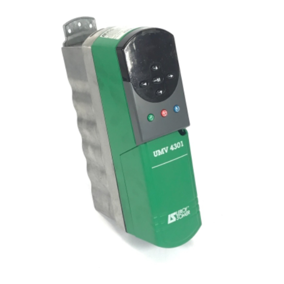
Leroy-Somer UMV 4301 Manual (113 pages)
Open and closed loop speed controllers for asynchronous and synchronous motors
Brand:
Leroy-Somer
| Category:
Controller
| Size: 0.92 MB
Table of Contents
Caution
2
Note
2
Electrical Connection
3
Safety and Operating Instructions for Speed Controllers
3
Use
3
General
3
Menu Organisation
5
Contents
6
Table of Contents
7
List of Menu 1 Parameters
9
Selection, Limits and Filters
9
Menu 1 Synoptic Views
12
Selection of the Speed Reference
12
Limits and Filters
13
Offset Speed Reference
14
Explanation of Parameters in Menu 1
14
Maximum Speed Limit
14
Jog Reference
14
Drive Control Indicators
15
Selection of Bi-Directional Mode
15
Selection of Preset Speeds
15
Selection of Speed Reference Offset
15
Enabling the Precision Reference
16
Precision Reference
16
Skip Speeds
16
Width of Skip Speeds
16
Speed Reference from Synchro Mode
17
Selected Reference Indicator
17
Preset Speed Cycle Reset
17
Adjustment of Speed Reference
17
List of Menu 2 Parameters
19
Ramps
19
Acceleration Ramps
20
Menu 2 Synoptic Views
20
Deceleration Ramps
21
Explanation of Menu 2 Parameters
22
Frequency or Speed Reference after Ramp
22
Ramp Enabling
22
S Ramp Enabling
22
Selection of Different FWD/REV Ramps
23
Selection of Acceleration and Deceleration Ramps
23
DC Bus Voltage Threshold
23
Jog Acceleration Ramp
24
Jog Deceleration Ramp
24
Selection of Ramps Via Logic Inputs
24
Selection of Reverse Acceleration and Deceleration Ramp
24
Encoder Input and Speed Loop
25
List of Menu 3 Parameters
25
Frequency Reference Via Encoder Input
27
Synoptic Views Menu 3
27
Explanation of Parameters in Menu 3
29
Final Speed Reference
29
Speed Feedback
29
Zero Speed Threshold
29
Speed Reached Alarm Condition Selection
30
Frequency Tracking Selection
30
Speed Loop Derivative Gain
30
Overspeed Threshold
30
Additional Speed Input
31
Encoder / Frequency Input Selection
31
Encoder Supply Voltage Selection
31
Output Frequency Adaptation
31
Encoder Phase Lead /Lag
32
Read Encoder Position
32
Read Encoder Speed
32
Selection of the Overspeed Threshold
32
Current Loop - Torque Regulation
33
List of Menu 4 Parameters
33
Open Loop
35
Menu 4 Synoptic Views
35
Closed Loop
36
Explanation of Menu 4 Parameters
37
Final Torque Reference
37
Motor Active Current
37
Total Motor Current
37
Current Loop Filter
38
Speed Control with Current Limiting Via Parameter
38
Torque Control
38
Torque Control with Speed Limiting
38
List of Menu 5 Parameters
39
Motor Control
39
Synoptic Views Menu 5
41
Motor Voltage
43
Explanation of Menu 5 Parameters
43
Motor Power
43
Motor Frequency
43
Motor Polarity
44
Power Factor
44
Selection of Dynamic U/F Mode
44
Self-Calibration
44
Jog Boost
45
Starting Torque (Boost)
45
Stator Resistance
45
Switching Frequency
45
Stability During Operation at Constant Power
46
Selection of Speed Resolution at 10 Min
46
Enable Quasi-Squared Modulation Mode
46
Enable High Stability Modulation Mode
46
Disabling the Torque Compensation in Reduced Flux Zone
47
Enable Slip Compensation
47
End of Rated Speed Setting
47
Voltage Regulation Gain
47
List of Menu 6 Parameters
49
Management of Logic Commands and Counters
49
Automatic Configuration of Terminal Block
50
Keypad Keys Enabling
50
Management of Logic Commands
50
Menu 6 Synoptic Views
50
Time Counter, Energy Meter and Alarms
51
Symbols
51
Start/Stop Command
51
Explanation of Menu 6 Parameters
52
Freewheel Stop
52
Selection of the Stopping Mode
52
2 (No.rp) : Stop Without Ramp
53
3 (Dcl) : Stop by DC Injection Braking, and Elimination at Zero Speed
53
3 (Rp.pos) : Orientation Stop (Indexing)
53
Automatic Starting Mode
54
DC Injection Braking Level
54
Microbreak Management
54
Minimum Jog Duration
54
Standstill Torque
55
Flying Restart
55
Controller Unlocking
55
Flying Restart Ramp
55
Alarm 2 and Counter Reset
56
Hour Counter
56
Operating Time before Alarm 2
56
Time Counter
56
Time to Return to the Reference Frequency
57
Voltage Applied During the Flying Restart Procedure
57
Assigning Analogue Inputs and Outputs
59
List of Menu 7 Parameters
59
Assigning Analogue Inputs
60
Menu 7 Synoptic Views
60
Speed Controller Environment
61
Selection of Signal Type Analogue Inputs
62
Analogue Input 1 Offset
62
Explanation of Menu 7 Parameters
62
Analogue Inputs
62
Analogue Output Sources
63
Automatic Scaling of Analogue Input 1
63
Input Inversion Bits
63
Scaling of the Analogue Outputs
63
Analogue Output Refresh Time
64
IGBT Junction Temperature
64
Indication of Presence of EPS UMV
64
Assigning Logic Inputs and Outputs
65
List of Menu 8 Parameters
65
Assigning Logic Inputs/Outputs
66
Menu 8 Synoptic Views
66
Assigning Logic Inputs and Relay Outputs
67
Explanation of Menu 8 Parameters
68
Reads the State of Terminal 30
68
Reads the State of the Output Relay
68
Selection of the Input on Terminal 30
68
Control Logic Polarity
69
Destination of the Inputs of Terminals 27 to 29
69
List of Menu 9 Parameters
71
Logic and Faster / Slower Command Functions
71
Logic Functions
72
Menu 9 Synoptic Views
72
Faster/Slower and Binary/Decimal Converter Function
73
Time Delay for and Function Outputs
74
Explanation of Menu 9 Parameters
74
Logic Inversion of and Function Outputs
74
Destination of and Function Outputs
74
Faster/Slower Inputs
75
Ramp Time Faster/Slower Command Reference
75
Selection Faster/Slower Reference Polarity
75
Selection of Automatic Reset of Faster/Slower Command Reference
75
List of Menu 10 Parameters
77
Speed Controller States and Diagnostics
77
Menu 10 Synoptic Views
78
Operating States
78
Braking Resistance and Fault Management Configuration
79
Resistance Braking
79
Trip Management
79
Speed Reference Reached
80
Controller Ready
80
Explanation of Menu 10 Parameters
80
Controller Running
80
Indication of Direction of Operation
81
Mains Lost
81
Motor Overheating
81
Overload Alarm
81
Controller Reset
82
External Trip
82
Maximum Braking Time at Full Power
82
Number of Automatic Resets
82
Time Delay before Automatic Reset
83
Operating State Maintained until Definitive Tripping
83
Designation of State
83
+ 24 V of EPS Module Active
83
List of Menu 11 Parameters
85
Setting Menu 0 - Serial Link - Controller Characteristics
85
Controller Configuration
86
Menu 0 Configuration (User Menu)
86
Menu 11 Synoptic Views
86
Serial Link
86
Explanation of Menu 11 Parameters
87
Parameter Displayed on Power-Up
87
Scaling of Parameter 1
87
Serial Link Address
87
Type of Communication
88
Transmission Speed
88
Scaling of the Variable
88
Communication Delay in " 2-Wire " Mode
88
Controller Rated Current
89
Controller Rated Voltage
89
Operating Mode
89
Selected Preset Configuration
89
Menu 12 : Programmable Thresholds
91
List of Menu 12 Parameters
91
Synoptic View Menu 12
92
Explanation of Menu 12 Parameters
93
State of Comparator Outputs
93
Sources of Variables
93
Threshold Adjustment
93
Menu 13 : Synchronisation and Indexing
95
List of Menu 13 Parameters
95
Menu 13 Synoptic Views
97
Explanation of Menu 13 Parameters
100
Position Loop Error
100
Encoder Reference Input
100
Encoder Max. Speed
100
Position Loop Gain
101
Position Error Correction Speed Limit
101
Indexing Reference
101
Sampling
101
Reference Encoder Revolution Counter
102
Feedback Encoder Revolution Counter
102
End of Indexing Signal
102
Explanation of Menu 13 Parameters
102
Menu 14 : Pid Controller
103
List of Menu 14 Parameters
103
Menu 14 Synoptic Views
104
Explanation of Menu 14 Parameters
105
PID Output
105
Inversion of Input Sign
105
PID Low Limit
105
PID Output Destination
106
Integral Locking
106
Symmetry of the PID High and Low Limits
106
Menu 15 : Reserve
108
Menu 16 : Small Option Module Parameter Setting
108
Menu 17 : Large Option Module Parameter Setting
108
Menu 18 : Application-Specific Parameters
108
Menu 20 : Application-Specific Parameters
109
Advertisement
Advertisement
Related Products
Leroy Somer UMV 2301 AS Series
Leroy Somer UMV 2301 AS 8T
Leroy Somer UMV 2301 AS 33T
Leroy Somer UMV 2301 AS 40T
Leroy Somer UMV 2301 AS 50T
Leroy Somer UMV 2301 AS 60T
Leroy Somer UMV 2301 AS 75T
Leroy Somer UMV 2301 AS 11T
Leroy Somer UMV 2301 AS 16T
Leroy Somer UMV 2301 AS 27T
Leroy-Somer Categories
Engine
Controller
Portable Generator
Industrial Equipment
Inverter
More Leroy-Somer Manuals
Login
Sign In
OR
Sign in with Facebook
Sign in with Google
Upload manual
Upload from disk
Upload from URL