Sign In
Upload
Manuals
Brands
Lenze Manuals
Inverter
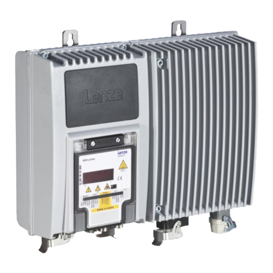
protec HighLine 8400
Lenze protec HighLine 8400 Manuals
Manuals and User Guides for Lenze protec HighLine 8400. We have
1
Lenze protec HighLine 8400 manual available for free PDF download: Reference Manual
Lenze protec HighLine 8400 Reference Manual (1582 pages)
Inverter Drives
Brand:
Lenze
| Category:
Inverter
| Size: 29 MB
Table of Contents
Table of Contents
3
About this Documentation
21
Document History
22
Conventions Used
23
Terminology Used
24
Definition of the Notes Used
26
Introduction: Parameterising the Inverter
27
Integrated Technology Applications
29
Purpose of the Technology Applications
30
Application Cases for a Technology Application
30
Technology Application = Function Block Interconnection
31
Selection of the Appropriate Commissioning Tool
32
Overview: Accessories for Commissioning
33
General Notes on Parameters
34
Changing the Parameterisation with the Keypad
35
Change Parameter Settings with PC and Lenze Software
38
Save Parameter Settings in the Memory Module Safe against Mains Failure
39
User Menu for Quick Access to Frequently Used Parameters
42
Device Access Protection
43
Password Protection
44
Device Personalisation
46
Unlocking the Inverter with a Masterpin
48
Device Identification
49
Automatic Acceptance of the Device Name in the "Engineer
49
Extended Item Designation
49
Commissioning
50
Safety Instructions with Regard to Commissioning
51
Commissioning Notes for External 24 V Supply
52
Notes on Motor Control
53
Preconditions for Commissioning with the "Engineer
54
Trouble-Shooting During Commissioning
55
Commissioning Wizard 8400
55
Commissioning of the "Actuating Drive Speed" Technology Application
57
Prepare Inverter for Commissioning
58
Creating an "Engineer" Project & Going Online
59
Parameterising the Motor Control
60
Parameterise Application
61
Save Parameter Settings Safe against Mains Failure
63
Enable Inverter and Test Application
63
Commissioning of the "Table Positioning" Technology Application
65
Prepare Inverter for Commissioning
66
Creating an "Engineer" Project & Going Online
68
Parameterising the Motor Control
69
Parameterise Application
70
Set Machine Parameters
71
Set the Position Encoder
72
Set Homing
74
Enter One or more Profiles
76
Save Parameter Settings Safe against Mains Failure
78
Enable Inverter and Test Application
78
Commissioning of the "Switch-Off Positioning" Technology Application
80
Prepare Inverter for Commissioning
82
Creating an "Engineer" Project & Going Online
83
Parameterising the Motor Control
84
Parameterise Application
85
Save Parameter Settings Safe against Mains Failure
87
Enable Inverter and Test Application
87
PC Manual Control
88
Activate PC Manual Control
88
Speed Control
91
Set/Reset Home Position
93
Manual Jog
94
Positioning (Relative or Absolute)
95
Device Control (DCTRL)
97
Device Commands (C00002/X)
99
Load Lenze Setting
102
Load All Parameter Sets
103
Save All Parameter Sets
104
Enable/Inhibit Inverter
105
Activate/Deactivate Quick Stop
106
Optional Settings
107
Reset Error
109
Delete Logbook
109
Device Search Function
110
Device State Machine and Device States
111
Firmwareupdate
112
Init
113
Ident
114
Safetorqueoff
115
Readytoswitchon
116
Switchedon
117
Operationenabled
118
Troubleqsp
119
Trouble
120
Fault
121
Automatic Restart after Mains Connection/Fault
122
Inhibit at Power-On" Auto-Start Option
122
Auto-Start Option "Inhibit at Lenze Setting
124
Internal Interfaces | "Ls_Driveinterface" System Block
125
Wcancontrol/Wmcicontrol Control Words
128
Wdevicestatusword Status Word
129
Energy Saving Mode
130
Motor Control (MCTRL)
132
Motor Selection/Motor Data
133
Selecting a Motor from the Motor Catalogue in the "Engineer
137
Automatic Motor Data Identification
139
Application Notes for Asynchronous Motors with High Slip Speed
148
Selecting the Control Mode
149
Selection Help
153
Defining Current and Speed Limits
154
V/F Characteristic Control (Vfcplus)
157
Parameterisation Dialog/Signal Flow
158
Basic Settings
160
Defining the V/F Characteristic Shape
161
Defining Current Limits (Imax Controller)
162
Optimising the Control Mode
163
Adapting the V/F Base Frequency
164
Adapting the Vmin Boost
166
Optimising the Imax Controller
167
Optimising the Stalling Behaviour
168
Torque Limitation
169
Defining a User-Defined V/F Characteristic
171
Remedies for Undesired Drive Behaviour
174
V/F Characteristic Control - Energy-Saving (Vfcpluseco)
175
Parameterisation Dialog/Signal Flow
176
Comparison of Vfcpluseco - Vfcplus
178
Basic Settings
179
Optimising the Control Mode
180
Improving the Behaviour at High Dynamic Load Changes
181
Adapting the Slope Limitation for Lowering the Eco Function
182
Optimising the Cos/Phi Controller
182
Remedies for Undesired Drive Behaviour
183
V/F Control (Vfcplus + Encoder)
185
Parameterisation Dialog/Signal Flow
186
Basic Settings
188
Parameterising the Slip Regulator
189
Sensorless Vector Control (SLVC)
192
Parameterisation Dialog/Signal Flow
193
Types of Control
195
Speed Control with Torque Limitation
195
Torque Control with Speed Limitation
197
Basic Settings
198
Optimising the Control Mode
199
Optimising the Starting Performance after a Controller Enable
199
Optimise Speed Controller
200
Optimising Dynamic Performance and Field Weakening Behaviour
201
Optimising the Stalling Behaviour
202
Optimise Response to Setpoint Changes and Determine Mass Inertia
203
Slip Calculation from Motor Equivalent Circuit Diagram Data
206
Optimising Field Feedforward Control and Torque Feedforward Control
207
Remedies for Undesired Drive Behaviour
208
Sensorless Control for Synchronous Motors (SLPSM)
209
Parameterisation Dialog/Signal Flow
210
Types of Control
214
Basic Settings
215
Optimising the Control Mode
217
Optimise Current Controller
218
Optimise Speed Controller
219
Optimise Response to Setpoint Changes and Determine Mass Inertia
222
Current-Dependent Stator Leakage Inductance Ppp(I)
225
Pole Position Identification Without Motion
227
Field Weakening for Synchronous Motors
229
Servo Control (SC)
232
Parameterisation Dialog/Signal Flow
233
Types of Control
236
Speed Control with Torque Limitation
236
Torque Control with Speed Limitation
238
Basic Settings
239
Parameterising the Encoder/Feedback System
240
Optimising the Control Mode
241
Optimise Current Controller
242
Optimise Speed Controller
243
Optimise Response to Setpoint Changes and Determine Mass Inertia
246
Setting the Current Setpoint Filter (Band-Stop Filter)
249
Adapting the Max. Acceleration Change (Jerk Limitation)
250
Slip Calculation from Motor Equivalent Circuit Diagram Data
251
Optimising the Behaviour in the Field Weakening Range
252
Feedforward Control of the Current Controller
257
Parameterisable Additional Functions
258
Selection of Switching Frequency
258
Operation with Increased Rated Power
262
Flying Restart Function
264
DC-Injection Braking
267
Manual DC-Injection Braking (DCB)
269
Automatic DC-Injection Braking (Auto-DCB)
269
Slip Compensation
272
Oscillation Damping
273
Oscillation Damping Voltage Range
274
Oscillation Damping in the Field Weakening Range
275
Phase Sequence Reversal for Correcting Misconnected UVW Motor Phases
276
Encoder/Feedback System
277
Parameterising Digital Inputs as Encoder Inputs
281
Encoder Evaluation Method
282
Generation of the Actual Speed Value
283
Encoder with HTL Level at DI1/DI2
284
Encoder with HTL Level at DI5/DI6
286
SSI Encoder Evaluation
287
Important Notes for Using an SSI Laser Position Encoder
291
Configuration Example 1: Optical Multi-Turn Rotary Encoder "G0M2H Z04" by Baumer
292
Configuration Example 2: Distance Sensor "DME5000-111" by Sick
293
Evaluation of External Absolute Value Encoders
295
Position Control/Additive Speed Specification
296
Braking Operation/Brake Energy Management
297
Setting the Voltage Source for Braking Operation
300
Selecting the Response to an Increase of the DC-Bus Voltage
301
Inverter Motor Brake
303
Avoiding Thermal Overload of the Brake Resistor
306
Control of Multiple Internal Brake Choppers in the DC-Bus System
306
Monitoring
309
Device Overload Monitoring (Ixt)
310
Motor Overload Monitoring (I2Xt)
310
Motor Overcurrent Monitoring
312
Motor Temperature Monitoring (PTC)
313
Brake Resistor Monitoring (I2Xt)
314
Motor Phase Failure Monitoring
316
Motor Phase Error Monitoring before Operation
317
Mains Phase Failure Monitoring
319
Maximum Current Monitoring
319
Current Monitoring for Overload
320
Maximum Torque Monitoring
321
Motor Speed Monitoring
321
Encoder Value Monitoring
321
Encoder Open-Circuit Monitoring
322
Internal Interfaces | System Block "Ls_Motorinterface
323
Internal Status Signals | System Block "Ls_Devicemonitor
329
I/O Terminals
331
Digital Terminals
332
Change Function Assignment
334
Using DI1(5) and DI2(6) as Digital Inputs
335
Using DI1(5) and DI2(6) as Frequency Inputs
336
Using DI1(5) as Counting Input
341
Reconfiguring DI3(4) to Output DO1(2)
345
Internal Interfaces | System Block "Ls_Digitalinput
347
Output of the Encoder Position of the DI1/DI2 Frequency Input
350
Internal Interfaces | System Block "Ls_Digitaloutput
354
Analog Terminals
355
Parameterising Analog Input
356
Signal Adaptation by Means of Characteristic
357
Internal Interfaces | System Block "Ls_Analoginput
359
Touch Probe Detection
360
Parameter Setting
362
Internal Interfaces | System Block "Ls_Touchprobe
365
Application Example: "Position Measurement
366
Configuring Exception Handling of the Output Terminals
367
User-Defined Terminal Assignment
368
Source-Destination Principle
369
Changing the Terminal Assignment with the Keypad
370
Changing the Terminal Assignment with the "Engineer
372
Technology Applications
375
Selection of the Technology Application and the Control Mode
376
TA "Actuating Drive Speed
377
Basic Signal Flow
378
Internal Interfaces | Application Block "La_Nctrl
380
Terminal Assignment of the Control Modes
388
Terminals 0
388
Terminals 2
388
Terminals 11
389
Terminal 16
392
Keypad
393
Can
395
MCI
396
Process Data Assignment for Fieldbus Communication
397
Setting Parameters (Short Overview)
399
Configuration Parameters
401
TA "Table Positioning
404
Basic Signal Flow
405
Possibilities for the Position Selection
406
Internal Interfaces | Application Block "La_Tabpos
408
Terminal Assignment of the Control Modes
418
Terminals 0
418
Terminals 2
418
Terminals 11
419
Terminal 16
420
Keypad
423
Can
425
MCI
426
Process Data Assignment for Fieldbus Communication
427
Setting Parameters (Short Overview)
429
Configuration Parameters
430
TA "Switch-Off Positioning
433
Basic Signal Flow
435
Internal Interfaces | Application Block "La_Switchpos
436
Truth Table for Activating the Pre-Switch off
443
Terminal Assignment of the Control Modes
444
Terminals 0
444
Terminals 2
444
Terminals 11
445
Terminal 16
448
Keypad
449
Can
451
MCI
452
Process Data Assignment for Fieldbus Communication
453
Setting Parameters (Short Overview)
455
Configuration Parameters
457
Generalpurpose" Functions
460
Analog Switch
460
Arithmetic
461
Multiplication/Division
461
Binary Delay Element
462
Binary Logic
462
Analog Comparison
463
Binary Signal Monitor
463
Analog Signal Monitor
464
D-Flipflop
464
Counter
465
Basic Drive Functions (MCK)
466
Basic Signal Flow
467
Internal Interfaces | System Block "Ls_Motioncontrolkernel
468
MCK Control Word
474
MCK Status Word
476
Status Bit "Homposavailable
478
Status Bit "S_Shapingactive
479
Status Bit "Breadytooperate
480
MCK State Machine
481
Standby" Operating Mode
482
Interface to Safety System
483
Consideration of Residual Value in Case of External Profile Calculation
484
Mckinterface
485
Control Inputs | "L_Mckctrlinterface" Function Block
487
Alternative Functions for Control Bit "Posexecute
492
Operating Mode Change with Profile Number
493
Status Outputs | FB "L_Mckstateinterface
494
Basic Settings
496
Machine Parameters
496
Gearbox Ratio
498
Feed Constant
499
Activation of the Modulo Measuring System
500
Min/Max Speed
503
Limit Position Monitoring
504
Software Limit Positions
504
Hardware Limit Switches
507
Target Position Monitoring (Status "Drive in Target")
509
Monitoring of the Maximum Travel Distance
511
Following Error Monitoring System
512
Monitoring of the Following Error in Case of Controller Inhibit
513
Setpoint Holdback for Bus Runtime Compensation
514
Setting or Activation of Maximum Jerk for Traversing Profiles
518
Speed Follower
519
Parameter Setting
519
Functional Settings
519
Requesting the Operating Mode
520
Setpoint Selection
520
Homing
521
Parameter Setting
522
Functional Settings
523
Referencing Mode
524
Home Position & Home Value Offset
536
Traversing a Sequence Profile after Completion of Homing
536
Measurement of the Distance between Pre-Stop Mark/Limit Switch and TP/MP
536
Option "Actual MCTRL Position Received at Mains Switch-Off
537
Requesting the Operating Mode
537
Execute Homing
538
Homing on the Fly
539
Manual Jog
540
Parameter Setting
541
Functional Settings
542
Smooth Start and Quick Stop of the Drive
543
Second Speed
543
Time-Based Start of Second Speed
544
Requesting the Operating Mode
545
Executing Manual Jogging
545
Manual Jog to Limit Position
546
Retracting of an Operated Limit Switch
547
Positioning
548
Possible Motion Profiles
549
Parameter Setting
550
Functional Settings
551
Profile Entry
552
Positioning Modes
555
Touch Probe Positioning
556
S-Ramp Time for Jerk Limitation
557
Requesting the Operating Mode
559
Carrying out Positioning
559
Stipulation of the Profile to be Executed
559
Starting/Cancelling a Traversing Task
560
Override of the Parameterised Positioning Mode
561
Position Teaching
562
Stop
563
Parameter Setting
563
Requesting the Operating Mode
563
Position Follower
564
Parameter Setting
565
Functional Settings
565
Requesting the Operating Mode
566
Setpoint Selection
566
Override
567
Speed Override
568
Acceleration Override
569
S-Ramp Smoothing Override
570
Holding Brake Control
571
Internal Interfaces
572
Parameter Setting
574
Operating Mode
575
Functional Settings
577
Switching Thresholds
578
Application and Release Time
579
Ramp Time for Approaching the Setpoint Speed
581
Motor Magnetising Time (Only with Asynchronous Motor)
582
Actual Value Monitoring
582
Process When Brake Is Released
583
Process When Brake Is Closed
584
Behaviour in Case of Pulse Inhibit
586
Feedforward Control of the Motor before Release
587
Diagnostics & Error Management
589
Basics on Error Handling in the Inverter
589
LED Status Displays
590
LED Status Displays of the Device Status
592
Drive Diagnostics Via the Integrated 7-Segment Display
593
Drive Diagnostics with the "Engineer
596
Display Details of the Error
598
Drive Diagnostics Via Keypad/Bus System
599
Logbook
602
Functional Description
602
Filtering Logbook Entries
603
Automatic Recording of Device-Internal Signals at the Time the Error Occurs
604
Reading out Logbook Entries
605
Exporting Logbook Entries to a File
606
Storing the Logbook in the Project
607
Reading out the Logbook from an External Control/Visualisation
608
Monitoring
610
Monitoring Configuration
611
Setting the Error Response
612
Autofailreset Function
613
Maloperation of the Drive
614
Operation Without Mains Supply
616
Error Messages of the Operating System
617
Structure of the 32-Bit Error Number (Bit Coding)
617
Structure of the 16 Bit Error Number (Bit Coding)
620
Reset Error Message
621
Export Error Texts
622
Short Overview (A-Z)
623
Cause & Possible Remedies
626
Ls_Seterror_1" System Block
650
Ls_Seterror_2" System Block
651
Oscilloscope Function
652
Technical Data
653
Operation
653
User Interface
654
Selecting the Signal Sources to be Recorded
656
Selecting the Recording Time/Sample Rate
657
Selecting the Trigger Condition
657
Starting Recording
659
Cyclic Recording
659
Adjusting the Representation
659
Cursor Function: Reading Individual Measured Values
661
Last Settings
662
Managing Oscillograms
663
Commenting the Oscillogram
663
Saving the Oscillogram in a File
664
Loading the Oscillogram File
665
Overlay Function
666
Deleting an Oscillogram File Saved in the Project
667
Canopen Option
668
General Information
669
General Data and Application Conditions
669
Supported Protocols
670
Communication Time
671
Possible Settings Via DIP Switch
672
Activating the Bus Terminating Resistor
672
Setting the Baud Rate
673
Setting the Node Address
673
LED Status Displays for the System Bus
674
Going Online Via the System Bus
675
Reinitialising the Canopen Interface
675
Structure of the CAN Data Telegram
676
Identifier
676
User Data
678
Communication Phases/Network Management
679
Status Transitions
680
Network Management Telegram (NMT)
681
Parameterising the Inverter as CAN Master
682
Process Data Transfer
683
Available Process Data Objects
684
RPDO1 | "Lp_Canin1" Port Block
685
RPDO2 | "Lp_Canin2" Port Block
687
RPDO3 | "Lp_Canin3" Port Block
689
RPDO4 | "Lp_Canin4" Port Block
691
TPDO1 | "Lp_Canout1" Port Block
693
TPDO2 | "Lp_Canout2" Port Block
694
TPDO3 | "Lp_Canout3" Port Block
695
TPDO4 | "Lp_Canout4" Port Block
696
Identifiers of the Process Data Objects
697
Transmission Type
699
Synchronisation of Pdos Via Sync Telegram
701
Monitoring of the Rpdos for Data Reception
702
Configuring Exception Handling of the CAN Pdos
702
Parameter Data Transfer
704
Identifiers of the Parameter Data Objects
705
User Data
705
Command
706
Addressing by Means of Index and Subindex
707
Data 1
708
Error Messages
709
Parameter Data Telegram Examples
711
Read Parameters
711
Write Parameters
712
Read Block Parameters
713
Monitoring
716
Integrated Error Detection
716
Heartbeat Protocol
717
Telegram Structure
717
Parameter Setting
718
Commissioning Example
719
Emergency Telegram
720
Canopen Objects Implemented
721
Internal Interfaces | System Block "Ls_Canmanagement
747
PROFIBUS/PROFINET Option
748
Selection of the Communication Option
748
Parameter Setting
748
Process Data Transfer
749
Control Mode "MCI
751
Port Block "Lp_Mciin
752
Port Block "Lp_Mciout
753
CAN Gateway
754
Synchronisation of the Internal Time Base
755
Internal Interfaces | System Block "Ls_Syncmanagement
756
Drive-Based Safety
757
Selection of the Safety Option
758
Parameter Setting
758
Integration into the Application
759
Internal Interfaces | System Block "Ls_Sminterface
760
Status Information
760
I/O Status Information
761
Control Information
761
Transferring the Control Information to the Application
762
Interconnection Examples
763
Parameter Change-Over
766
Configuring Parameter Change-Over Via the "Engineer" Parameterisation Dialog
767
Configuring the Parameter List(S)
768
Configuring Control Inputs
771
Functional Settings
771
Error Message
772
Configuring the Definable Parameter List by Means of Parameterisation
773
Configuring the Motor Data Parameter List by Means of Parameterisation
774
Internal Interfaces | System Block "Ls_Writeparamlist
777
Parameter Reference
779
Structure of the Parameter Descriptions
780
Data Type
781
Parameters with Read-Only Access
781
Parameters with Write Access
782
Parameters with Setting Range
782
Parameters with Selection List
782
Parameters with Bit-Coded Setting
783
Parameters with Subcodes
784
Parameter Attributes
784
Parameter List
786
Selection List - Analog Signals
1138
Selection List - Digital Signals
1144
Selection List - Angle Signals
1151
Table of Attributes
1153
Working with the FB Editor
1170
Basics
1170
Basic Components of a Drive Solution
1171
What Is a Function Block
1172
Parameterisable Function Blocks
1173
What Is a System Block
1173
What Is a Port Block
1174
What Is an Application Block
1174
Conventions Used for Input/Output Identifiers
1175
Scaling of Physical Units
1176
User Interface
1177
Toolbar
1178
Search Function
1179
Plane Selection
1180
Editor View/Overview
1182
Context Menu
1183
Status Bar
1183
Overview
1184
Using the FB Editor as "Viewer
1186
Following Connections of Inputs and Outputs
1187
Keyboard Commands for Navigation
1188
Change Online Display Format
1189
Advertisement
Advertisement
Related Products
Lenze P500 series
Lenze P30GAP Series
Lenze P30GAH Series
Lenze P50GAP series
Lenze MOBILE PSU
Lenze PROFINET 9400
Lenze Drive PLC
Lenze p300
Lenze PROFIBUS-DP
Lenze PT-1
Lenze Categories
DC Drives
Control Unit
Inverter
Engine
Controller
More Lenze Manuals
Login
Sign In
OR
Sign in with Facebook
Sign in with Google
Upload manual
Upload from disk
Upload from URL