Sign In
Upload
Manuals
Brands
LeCroy Manuals
Test Equipment
DDA 7 Zi series
LeCroy DDA 7 Zi series Manuals
Manuals and User Guides for LeCroy DDA 7 Zi series. We have
1
LeCroy DDA 7 Zi series manual available for free PDF download: Operator's Manual
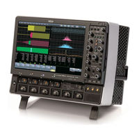
LeCroy DDA 7 Zi series Operator's Manual (544 pages)
Oscilloscopes
Brand:
LeCroy
| Category:
Test Equipment
| Size: 13.13 MB
Table of Contents
Table of Contents
4
Compatible Options and Accessories
23
Comprehensive Core Functions (1000Base-T through Vertical)
23
Reference
23
Support
23
Thank You
23
Wavepro 700Zi Features
23
Cable De-Embedding
24
Setting up Cable De-Embedding
24
Saving Cable Configurations
24
Sequence Display Modes
26
Setting up Sequence Mode
26
Zooming Segments in Sequence Mode
28
Displaying an Individual Segment
29
Viewing Time Stamps
29
Spectrum Analyzer
30
Running the Spectrum Analyzer
30
Triggerscan
31
Training Triggerscan
32
Starting Triggerscan
33
Saving Triggerscan Setups
33
Front Panel
34
Detaching and Attaching the Front Panel
35
Side Panel
36
External Monitor
38
Combining Channels
40
Front Panel Controls
40
Miscellaneous Setup Controls
42
Trigger Front Panel Controls
42
Horizontal Front Panel Controls
43
Vertical Front Panel Controls
43
Cursors Front Panel Controls
43
Wavescan Front Panel Controls
44
General Controls Front Panel Controls
45
Zoom and Math Front Panel Controls
45
Menu Bar
46
The Signal Display Grid
46
Front Panel Groupings
47
Dialog Area
47
Universal Probus/Prolink Interface
49
Connecting the Adapters
50
Auxiliary Output Signals
51
Auxiliary Output Setup
51
Pass/Fail Testing
51
Comparing Parameters
52
Mask Tests
52
Actions
53
Pass/Fail Testing Setup
53
Signal Views
56
Search Modes
56
Parameter Measurements
57
Sampling Mode
57
Level Markers
57
Scan Overlay
58
Source View
58
Scan Histogram
59
Zoom View
60
Edge Mode
61
Scan Filters
65
Filter Wizard
65
Filter Methods
66
Auxiliary Output Setup
67
Auxiliary Output Signals
67
Examples
69
Golden Waveforms
73
Scaling and Display
73
A Practical Example – DVI Data-Clock Skew
74
Entering a File Name
75
Simple Excel Example 1
77
How Does this Work
85
Example Waveform Function Script: Square of a Waveform
89
Example Parameter Function Script: RMS of a Waveform
90
The Default Waveform Function Script: Explanatory Notes
90
Solutions
69
Errors
93
Speed of Execution
95
MATLAB Parameter Editor
105
Display Setup
106
Sequence Sampling Mode – Working with Segments
107
Sequence Mode Display
107
Custom Grids
108
Previewing Zoomed Waveforms
109
XY Display
108
Setting up XY Displays
108
Quickly Zooming Multiple Waveforms
109
Multi-Zoom
110
Persistence Setup
111
Setting up Persistence
111
Setting up 3-Dimensional Persistence
113
Show Last Trace
113
Persistence Time
114
Setting up a Single Parameter Histogram
114
Viewing Thumbnail Histograms (Histicons)
115
Persistence Histogram (JTA2 Option)
115
Persistence Trace Range
115
Persistence Sigma
116
DSO Process
117
Parameter Buffer
117
Capture of Parameter Events
117
Histogram Parameters (XMAP and JTA2 Options)
118
Histogram Peaks
118
Binning and Measurement Accuracy
119
Full Width at Half Maximum
119
Full Width at XX% Maximum
120
Histogram Amplitude
121
Histogram Root Mean Square
122
Histogram Top
122
Maximum Population
123
Mode
123
Peaks
124
Range
125
Percentile
124
Total Population
126
System Recovery for Oscilloscopes Running Windows XP and Vista
127
Recovery Procedure
127
Restarting the Application
131
Restarting the Operating System
131
Removable Hard Drive
131
Preferences
132
Setting Preferences
132
Creating a Report
137
Previewing a Report
137
Locating a Notebook Entry
137
Creating the Report
138
Formatting the Report
138
Adding Annotations
138
Deleting Notebook Entries
139
Saving Notebook Entries to a Folder
139
Managing the Database
139
Setting up a Math Function
141
Deskewing
142
Rescaling Setup
143
Summed Vs. Continuous Averaging
143
Setting up Continuous Averaging
144
Setting up Summed Averaging
144
Enhanced Resolution
144
How the Instrument Enhances Resolution
145
Setting up Enhanced Resolution (ERES)
146
Interpolation
147
Setting up Interpolation
147
Waveform Sparser
147
Waveform Sparser Setup
147
Demodulation
148
Theory of Operation
148
Setting up Demodulation
148
Setup - Case 1
151
Setup - Case 2
151
Setup - Case 3
151
Setting up an FFT
152
Power (Density) Spectrum
153
Memory for FFT
153
FFT Pitfalls to Avoid
153
Picket Fence and Scallop
153
Leakage
153
Choosing a Window
153
Improving Dynamic Range
154
Record Length
154
FFT Algorithms
155
To Use the Web Editor
158
Cursor Measurement Icons
160
Cursors Setup
161
Quick Display
161
Setting up Absolute Cursors
161
Setting up Relative Cursors
162
Cursors on Math Functions
162
Turning on Parameters
162
Quick Access to Parameter Setup Dialogs
162
Parameter Setup
162
Status Symbols
165
Measure Modes
167
Standard Vertical Parameters
168
Standard Horizontal Parameters
168
Selecting Measure Modes
168
Statistics
167
Parameter Math
168
Logarithmic Parameters
168
Excluded Parameters
169
Parameter Script Parameter Math
169
Setting up Parameter Math
171
Setting up Parameter Script Math
171
Measure Gate
171
Help Markers
173
Range Limited Parameters
195
Waveform Gated Parameters
196
Setting up the Printer
199
Adding Printers and Drivers
200
Hard Disk Partitions
200
Printing a Screen Image
200
Basic Capture Technique
201
Sampling Modes
201
Selecting a Sampling Mode
201
Roll Mode
202
Wavestream Mode
202
Adjusting Trace Intensity
203
Saving Scope Settings
203
Recalling Scope Settings
203
Recalling Default Settings
204
Saving Waveforms
204
Recalling Waveforms
206
Disk Utilities
206
Deleting a Single File
206
Deleting All Files in a Folder
206
Creating a Folder
207
Overview
207
Serial Decode
209
Serial Trigger
209
Serial Decode and Decode Setup
210
Table Display
210
Trigger
210
Decode Setup Dialog
212
Protocol Results Table
214
Setup Mode
219
Storing Triggers
230
Timebase Setup and Control
235
Setting up Additional Timebase Setup and Controls
235
Autosetup
236
Setting up Real Time (SMART) Memory
236
Aux Input Trigger
240
Aux Input Trigger Setup
240
Software Assisted Trigger
240
Trigger Types
241
Software Assisted Trigger Setup
241
Example
241
Trigger Settings
242
Edge Trigger Setup
243
Width Trigger
244
How Width Trigger Works
244
Width Trigger Setup
244
Qualified Trigger
245
How Qualified Triggers Work
245
Qualified First Trigger
246
Edge Qualified Trigger Setup
246
State Triggers
246
How Pattern Trigger Works
247
Pattern Trigger Setup
248
TV Trigger
249
TV Trigger Setup
249
Custom TV Standard Trigger Setup
250
SMART Triggers
251
Glitch Trigger
252
How Glitch Trigger Works
252
Glitch Trigger Setup
252
Interval Trigger
253
How Interval Triggers Work
253
Interval Trigger Setup
255
Dropout Trigger
256
How Dropout Trigger Works
256
Dropout Trigger Setup
256
Runt Trigger
257
Runt Trigger Setup
257
Slew Rate
258
Slew Rate Trigger Setup
259
Trigger Modes
260
Determining Trigger Level, Slope, Source, and Coupling
260
Trigger Source
261
Hold off by Time
262
Hold off by Events
262
Triggerscan
263
Training Triggerscan
263
Starting Triggerscan
264
Saving Triggerscan Setups
265
Remote Communication
265
Setting up Remote Communication
265
Configuring the Remote Control Assistant Event Log
266
Status
265
Accessing the System Status Dialog
265
Hardcopy
266
Printing
266
Clipboard
266
File
266
E-Mail
267
Setting up Auxiliary Output
268
Auxiliary Output Signals
268
Date and Time
268
Setting the Date and Time Manually
268
Setting the Date and Time from the Internet
268
Setting the Date and Time from Windows
269
Options
269
Enabling Audible Feedback
269
Preferences
269
Configuring E-Mail Settings
270
Enabling Auto-Calibration
270
Optimizing Performance
270
Setting a Delay Control
270
Setting an Offset Control
270
Acquisition Status
271
Service
271
Show Windows Desktop
271
Touch Screen Calibration
271
Adjusting Sensitivity
272
Adjusting the Waveform's Position
272
Coupling
272
Overload Protection
272
Setting Coupling
272
Probe Attenuation
272
Setting up Probe Attenuation
272
Bandwidth Limits
273
Setting Bandwidth Limits
273
Interpolation Setup
273
Inverting Waveforms
273
Using Find Scale
273
Variable Gain
273
Enabling Variable Gain
274
Channel Deskew
274
Channel Deskew Setup
274
Dark Calibration
275
Performing Dark Calibration
275
Histogramming
275
Trending
275
BES or EES Table
276
Histogram Trace Setup Dialog
282
Selecting the Histogram Function
282
Setting Binning and Histogram Scale
283
To Configure a Trend
284
Capture of Parameter Events
285
How to Read Trends
285
Parameter Buffer
285
Trend Calculation
285
Configuration Options
286
Description
292
Display Options
293
Description
294
Display Options
294
Description
295
Display Options
296
Display Options
297
Display Options
298
Description
299
Display Options
300
Description
301
Display Options
301
Description
302
Display Options
302
More on Edge Shift
303
Description
304
Display Options
304
Description
305
Display Options
305
Description
306
Display Options
306
Display Options
307
Description
308
Description
309
Display Options
309
Display Options
310
Description
311
Display Options
311
Description
312
Display Options
312
Description
313
Description
314
Display Options
314
Display Options
315
Description
316
Display Options
316
Description
317
Display Options
317
Description
320
Description
322
Display Options
323
More about Timing Jitter
324
Choice of Signals
325
Coupling
325
Threshold Selection
325
Histogram Parameters
331
Example
333
Equalized
335
Slicer
335
Operational Notes
336
Leveled
337
Sliced
338
Description of Encoding and Decoding
342
Running Disparity
342
Example 1
354
First Example Plugin – Exchanging Two Traces on the Grids
354
Example 2
357
Second Example Plugin – Log-Log FFT Plot
357
The Need
359
The Solution
359
Enhanced Solutions
360
Communications Channel Filters
362
IIR Filters
363
Filter Setup
364
DFP Filter Setup
364
Custom Filters
365
Custom Filter Setup
365
Example 1: Creating an FIR Filter Coefficient File Using Mathcad
365
Example 2: Creating an IIR Filter Coefficient File Using Mathcad
367
Multirate Filters
369
Description
369
Specifications
369
Compatibility
370
Probing
371
Operation
371
Selecting a Standard
371
Test Setup
371
Adding Measurements to a Mask Test
372
Custom Pulse Mask Test Files
373
Timing Functions
377
Timing Parameters
378
Statistical Tools
378
Using "Clock" or "Data
378
Jittertrack or Trend
379
Clock or Data
380
Jitter Math Setup
381
Jitter Parameters Setup
382
Selecting the Math Function
383
Setting up the Histogram
384
An Innovative Visual and Processing Tool
385
To Set up Trace Persistence
385
The Basic Idea
387
To Set up and Configure Trend
388
Acquisition Sequence
390
Parameter Buffer
390
Parameter Events Capture
390
Zoom Traces and Segmented Waveforms
391
Binning and Measurement Accuracy
391
Serial Data Analyzer Standard and Optional Capabilities
392
Histogram Peaks
391
Jitter Wizard
394
SDA Basic Setup
396
Mask Test
399
Eye Setup
399
Summary
399
Setting the Vertical Scale
401
Mask Margin
401
Testing
401
Bit Error Rate
403
Pj Breakdown
404
Effective Jitter
404
MJSQ Jitter
405
Bathtub Curve
406
Jitter Filter
407
TIE Histogram
408
Adjust Rj
413
Async N Cycle Plot
413
Edge-Edge Spacing Controls
413
Altncycle
414
Altncycle Control Summary
414
Jitter Filter Function
417
Slice2Persist
417
Eye Violation Locator (ASDA Option)
421
Eye Amplitude
421
Eye Height
422
Eye Width
422
Extinction Ratio
422
Eye Crossing
422
Average Power
422
Eyeber
423
Bit Error Rate and Jitter
424
Total Jitter
425
Extrapolating the PDF
426
Separating Rj and Dj – Two Methods
427
Effective Random and Deterministic Jitter
428
Direct Measurement of Deterministic Jitter
428
Bit Error Map
430
Bit Error Rate
430
Jitter Measurement
431
Introduction
431
Signal Slew Rate and How Vertical Noise Converts to Jitter
432
The Relative Impact of Noise on Jitter (Quadratic Addition of Noise)
432
How the Measurement System Noise Is Subtracted from the Jitter Measurement
432
Introduction
433
FSB Eye Mode Configuration
443
Introduction to FSB
445
FSB Theory of Operation
445
DDA Quick Access Toolbar Button
449
Additional DDA Triggers
449
Disk Drive Measurement Package (DDM2)
450
Automated DDA Measurements
450
Advanced DDA Analysis
451
Obstacles that Can be Overcome Using the Dda's Channel Analysis
451
What Channel Analysis Provides
451
Channel Emulation
452
With or Without Reference
452
Analog Compare
453
Measure's Drive Parameters
454
Drive Analysis Setup
454
Channel Setup
455
Drive Analysis Setup
457
Channel Setup
457
Read Gate
458
Sector Pulse
459
Servo Gate
459
Using the Dda's Equalization Filter
461
Selecting the Waveform Section to be Analyzed
461
Which Signals to Provide
463
Choosing the Waveform Section to be Analyzed
463
Selecting the Reference Waveform
464
Time/DIV Settings
464
Automatically Shown Traces
465
Setting Bit Cell Time
465
Retraining the Filter
465
Analog Compare
465
Channel Emulation with Reference
466
Channel Emulation Without Reference
466
Channel Emulation with Reference
468
Notes on Using Channel Emulation Without Reference
468
Notes on Using Channel Emulation with Reference
470
Notes on Using Head/Analog Compare
471
Overview
472
Local Feature Parameters
472
Disk Standard Parameters
482
Correlation Theory of Operation
486
Notes
490
Noise Parameters
491
Why PRML
493
Principle of Equalization
494
Resampling ADC
496
Finite Impulse Response (FIR)
496
Phase Locked Loop (PLL)
496
Automatic Gain Control (AGC)
496
ML Detector
497
Viterbi Detector & Trellis
497
Encoding
498
Error Correction
498
Loading Your UDT File Remotely
499
General Rules and Error Messages
499
Keywords
499
Example File
504
Probe Calibration with the TF-DSQ Fixture
505
TF-DSQ Fixture Overview
506
TF-DSQ Scope Connection
506
Probe Calibration Menu
511
Accessing the Probe Calibration Menu
511
Probe Calibration Menu Description
511
Basic Probe Calibration
513
Gain/Offset Only Calibration
513
Deskew Only
513
The Advanced Menu
514
Rise Time Skew Correction
514
Deskew All (or Common Skew)
514
Common Mode Voltage Selection
514
Differential and Single-Ended Probe Basics
514
Technical Support
526
Safety Symbols
527
Operating Environment
528
Cooling
528
AC Power Source
529
Power and Ground Connections
529
Standby (Power) Switch and Oscilloscope Operational States
529
Calibration
530
Cleaning
530
Abnormal Conditions
530
Base and Top Calculation
531
Configuration Menus
531
DVD Processing Model
531
DVD Ram
531
Nt Pit-Space Categorization
531
Averaging Waveforms
532
Back Panel
532
Selecting Parameters
532
Setup and Measurement Dialog
532
View Modes
532
Default Parameter Function Script
533
Error Handling
533
Exponential Decay Time Constant
533
Multiple Inputs and Outputs
533
Trace Descriptors
533
DDA Specifications
534
DDJ (Synchronous N-Cycle Plot)
534
Dual Channel Acquisition
534
EMC Parameters
534
FFT Setup
535
Glossary
535
Group Delay Compensation
536
Hardware and Software Controls
536
Histogram and Trend Calculation
536
Introduction to 8B/10B
536
Level and Slope
537
List of Parameters
537
Managing Files
537
Optimizing for High Frequency
538
Parameter Status
538
Qualified Parameters
539
Printing
539
Restoring Software
539
Screen Layout, Groupings, and Controls
539
Using Analog Compare
539
Htie to BER
540
Jitter Measurements
540
Jitter Setup
540
PLL Setup
540
Q-Scale Theory
540
Address Setup
541
Searching for Messages
541
Single-Shot Sampling Mode
541
TD Series Software
541
TF-DSQ Overview
542
Measurement Mode
543
Non-Monotonic Mode
543
Runt Mode
543
Welcome
543
Zooming Waveforms
543
Advertisement
Advertisement
Related Products
LeCroy DDA-3000A
LeCroy DDA-5005A
LeCroy DA1855A
LeCroy DA18000
LeCroy DA18000AC
LeCroy DXC100A
LeCroy 4300B
LeCroy 6000 SERIES
LeCroy 9300C Series
LeCroy 9344C Series
LeCroy Categories
Test Equipment
Measuring Instruments
Amplifier
Recording Equipment
Accessories
More LeCroy Manuals
Login
Sign In
OR
Sign in with Facebook
Sign in with Google
Upload manual
Upload from disk
Upload from URL