Sign In
Upload
Manuals
Brands
Leadshine Manuals
Servo Drives
EL6-RS Series
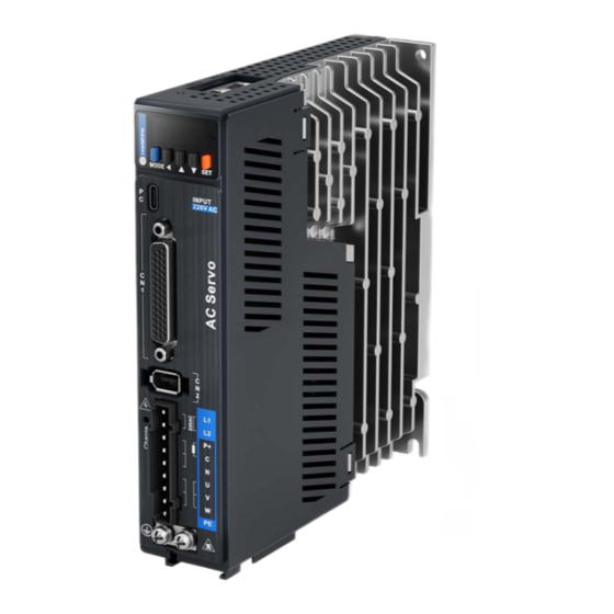
Leadshine EL6-RS Series AC Servo Drive Manuals
Manuals and User Guides for Leadshine EL6-RS Series AC Servo Drive. We have
1
Leadshine EL6-RS Series AC Servo Drive manual available for free PDF download: User Manual
Leadshine EL6-RS Series User Manual (305 pages)
AC Servo Drive
Brand:
Leadshine
| Category:
Servo Drives
| Size: 7 MB
Table of Contents
Warranty Information
5
Table of Contents
6
Chapter 1 Introduction
10
Product Introduction
10
Model Number Structure
11
Servo Drive
11
Servo Motor
12
Servo Drive Technical Specifications
13
Servo Drive Ports and Connectors
16
Motor Ports and Connectors
18
Chapter 2 Installation & Wiring
19
Servo Drive Installation
19
Servo Drive Installation Environment
19
Servo Drive Dimension
19
Servo Motor Installation
21
Installation Conditions
21
Precautions During Installation
21
El6-Rs Wiring Diagram
22
Position Control Mode Wiring Diagram
23
Servo Drive Ports
24
X1 Main Power Supply
25
Main Power Supply Cable Selection
26
Motor Power Supply Cable Selection (Without Brake)
28
Holding Brake Wiring Diagram
29
Motor Power Supply Cable (with Holding Brake)
30
Cn1 I/O Control Signal
32
CN1 Control Signal Cable Selection
34
Cn2 Motor Encoder
34
Cn3/Cn4 - Rs485 Communication Port
37
USB Type-C Tuning Port
38
Regenerative Resistor Selection and Connections
38
I/O Signals
44
Pulse Input Circuit
44
Digital Input Circuit
49
Digital Output Circuit
51
Encoder Frequency Divider Output Circuit
53
DI Signals Settings
55
Do Signals Settings
61
Measures against Electromagnetic Interference
64
Grounding Connection and Other Anti-Interference Wiring Connections
64
Using Line Filter
65
Chapter 3 Parameter
66
Parameters List
66
Parameters Description
76
Class 0] Basic Settings
76
Class 1] Gain Adjustments
87
Class 2] Vibration Suppression
93
Class 3] Velocity/Torque Control
99
Class 4] I/O Monitoring Settings
107
Class 5] Extension Settings
115
Class 6] Other Settings
123
Class 7] Factory Settings
127
Class B] Status Parameters
128
Class 8] PR Control Parameters
131
Class 9] PR Control Path Parameters
139
Chapter 4 Servo Drive Operation
155
Servo Enabled
155
Servo Stop
156
Front Panel
170
Panel Display and Operation
171
Panel Operation
171
Data Monitoring Mode
172
Parameters Saving
182
Auxiliary Function
183
Get Started with Driver Operation
188
Checklist before Operation
188
Power on
188
Trial Run
188
Chapter 5 Control Mode
189
Position Control
190
Pulse Input and Direction Settings
191
Electronic Gear Ratio
193
Position Command Filter
194
Frequency Divider Output
195
Positioning Completed INP Signal Output
197
Velocity Control Mode
198
Velocity Command Input Control
199
Velocity Command Acceleration/Deceleration
201
Velocity Reached Signal AT-SPEED Output
203
Velocity Coincidence V-COIN Signal Output
203
Zero Speed Clamp
204
Torque Control
205
Torque Command Input Control
206
Torque Velocity Limit
206
Torque Limit (TL-SEL)
207
Hybrid Control Mode
208
Chapter 6 Application Case
209
Gain Adjustment
209
Inertia Ratio Identification Function
211
Easy Tuning
215
Single Parameter Tuning
215
One-Click Tuning
216
Auto Gain Adjustment
218
Manual Gain Adjustment
223
Parameters Adjustment under Different Control Modes
225
Gain Switching
226
Rd Gain Switching
230
Model Following Control
231
Zero Tracking Control
232
Feedforward Gain
233
Velocity Feedforward
233
Torque Feedforward
234
Friction Compensation Function
236
Safety Functions
237
Max. Motor Rotational Speed Limitation
237
Max. Duration for Motor to Stop after Disabling
238
External Brake Deactivation Output Signal BRK-OFF
238
Servo Stopping Mode
240
Emergency Stop Function
241
Vibration Suppression
242
Mechanical Resonance Suppression
242
End Vibration Suppression
246
Mechanical Properties Analysis
247
Black Box
248
Multiturn Absolute Encoder
251
Parameters Setting
251
Read Absolute Position
251
Absolute Encoder Related Alarm
256
Chapter 7 Modbus Communication
257
Rs232 and Rs485 Connection Diagram
257
Rs485 Communication Port
258
Modbus Protocol
259
Read Data 0X03
259
Write Multiple Data 0X10
260
Frequently Occurred Issues and Solutions with Rs485 Communication
262
Chapter 8 Pr Functions
264
Pr Functions Introduction
265
Control Parameters
266
Pr Motion
268
Homing
268
Position Limit and Emergency Stop
273
Jog
273
Path Motion
274
Pr Control
277
PR Module in Motion Studio
277
Physical I/O
279
Communication
281
Path Trigger
282
Pr Motion
283
Trigger Using Physical I/O
283
Control Using 485 Communication
285
Chapter 9 Warning and Alarm
287
Servo Drive Warning
287
Servo Drive Alarm
288
Alarm Handling
291
Alarm Clearing
304
Servo Drive Alarm
304
Contact Us
305
Advertisement
Advertisement
Related Products
Leadshine EL6-CAN
Leadshine EL6-EC Series
Leadshine EL6-EC400
Leadshine EL6-EC750
Leadshine EL6-EC1000
Leadshine EL6-EC1500
Leadshine EL6-EC2000
Leadshine EL7-RS1500P
Leadshine EL7-PN400F
Leadshine EL7- PN2000F
Leadshine Categories
DC Drives
Servo Drives
Control Unit
Engine
Controller
More Leadshine Manuals
Login
Sign In
OR
Sign in with Facebook
Sign in with Google
Upload manual
Upload from disk
Upload from URL