Sign In
Upload
Manuals
Brands
Leadshine Manuals
Servo Drives
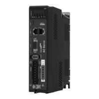
EL6-EC400
Leadshine EL6-EC400 Manuals
Manuals and User Guides for Leadshine EL6-EC400. We have
1
Leadshine EL6-EC400 manual available for free PDF download: User Manual
Leadshine EL6-EC400 User Manual (290 pages)
AC Servo Drive
Brand:
Leadshine
| Category:
Servo Drives
| Size: 6 MB
Table of Contents
Table of Contents
6
Chapter 1 Introduction
10
Product Introduction
10
Model Number Structure
11
Driver Technical Specification
12
Driver Ports and Connectors
14
Motor Ports and Connectors
16
Chapter 2 Installation & Wiring
17
Servo Drive Installation
17
Servo Drive Installation Environment
17
Servo Drive Dimension
17
Servo Motor Installation
20
Installation Conditions
20
Precautions During Installation
20
El6-Ec Wiring Diagram
22
Servo Drive Ports
24
X1 Main Power Supply
25
Regenerative Resistor Selection and Connections
26
Wire Gauge for Main Power Supply
31
Wiring Connections for EL6-EC Series Servo Drives
32
Connecting Motor Power Cable to Servo Drive
33
Holding Brake Connection
36
Cn2 Encoder
39
USB Type-C Tuning Port
43
CN3/CN4 Ethercat Communication Port
43
Cn1 I/O Signal Port
44
Selection of I/O Signal Cable
44
Common Input Circuit
45
Common Output Circuit
46
Probe Input Circuit
47
DI Signal Function Configuration
47
DO Signal Function Configuration
49
Measures against Electromagnetic Interference
50
Grounding Connection and Other Anti-Interference Wiring Connections
51
Using Line Filter
51
Chapter 3 Parameter
53
Parameter List
53
Servo Drive Parameter
53
Manufacturer Parameter
58
Motion Parameter Starting with Object Dictionary 6000
60
Parameter Function
63
Class 0】Basic Settings
63
Class 1】Gain Adjustments
70
Class 2】Vibration Suppression
76
Class 3】Velocity Control
83
Class 4】I/O Interface Setting
85
Class 5】Extension Settings
90
Class 6】Other Settings
94
Parameters Function
100
Chapter 4 Servo Drive Operation
118
Get Started with Driver Operation
118
Checklist before Operation
118
Power on
118
Trial Run
118
Motor Rotational Direction Settings
119
Holding Brake Settings
119
Servo Running
120
Servo Stop
122
Electronic Gear Ratio
134
Front Panel
135
Panel Display and Operation
136
Panel Operation
136
Data Monitoring Mode
137
Parameter Saving Using Front Panel
147
Auxiliary Functions
148
Chapter 5 Control Mode
153
EL6-EC Motion Control Step-By-Step
153
Cia 402 State Machine
154
Driver Control Mode Setting
156
Supported Control Mode (6502H)
156
Operational Mode Setting (6060H) and Operational Mode Display (6061H)
156
Common Functions for All Modes
156
Digital Input Setting and Status Display
156
Digital Output Setting and Control Operation Method
157
Motor Rotational Direction
157
Stop Settings
158
Position Mode - Electronic Gear
158
Position Limits
159
Control Word
160
Status Word
161
Synchronous Cycle Time Setting
162
Driver Enabling
162
Position Mode(Csp、Pp、Hm
163
Common Functions of Position Mode
163
Cyclic Synchronous Position Mode (CSP)
164
Protocol Position Mode (PP)
166
Homing Mode (HM)
169
Velocity Control Mode(Csv、Pv
193
Common Functions of Velocity Control
193
Cyclic Synchronous Velocity Mode (CSV)
194
Profile Velocity Mode (PV)
195
Torque Mode(Cst、Pt
197
Common Functions of Torque Mode
197
Cyclic Synchronous Torque Mode (CST)
198
Profile Torque Mode (PT)
199
Chapter 6 Application
202
Gain Adjustment
202
Inertia Measuring Function
204
Online Inertia Determination
204
Offline Inertia Determination
204
Auxiliary Function to Determine Inertia on Front Panel
205
Inertia Measuring Using Motion Studio
206
Auto Gain Adjustment
208
Manual Gain Adjustment
211
Gain Switching
213
Feedforward Gain
217
Velocity Feedforward
217
Velocity Feedforward Application
218
Torque Feedforward
218
Torque Feedforward Application
219
Model Following Control
220
Friction Compensation Function
221
Parameters Adjustment under Different Control Modes
222
Position Control Mode
222
Velocity Control Mode
223
Torque Control Mode
224
Safety Functions
224
Emergency Stop Function
225
Vibration Suppression
226
Mechanical Resonance Suppression
226
End Vibration Suppression
229
Mechanical Properties Analysis
230
Multiturn Absolute Encoder
231
Parameters Setting
231
Read Absolute Position
231
Absolute Encoder Related Alarm
236
Probe
237
Probe Function
238
Signal Input of EXT1 and EXT2
239
Probe Control Word 60B8H
239
Probe Status Word 60B9H
240
Latch Position Register
240
Latch Counter Register
241
Probe Mode
241
Other Functions
242
Functions under Position Mode
242
Functions under Velocity Mode
246
Functions under Torque Mode
249
Chapter 7 Ethercat Communication
250
Ethercat Principle Function
250
Synchronous Mode
251
Free Running Mode
251
Distributed Clock Synchronization Mode
251
Ethercat State Machine
252
Canopen over Ethercat (Coe)
253
Network Structure of EL6-EC
253
Object Dictionary
254
Service Data Object (SDO)
254
Process Data Object (PDO)
254
Chapter 8 Warning and Alarm
257
Servo Drive Warning
257
Servo Drive Alarm
257
Alarm Handling
265
Alarm Clearing
278
Servo Drive Alarm
278
Ethercat Communication Alarm
279
About Us
290
Advertisement
Advertisement
Related Products
Leadshine EL6-EC Series
Leadshine EL6-EC750
Leadshine EL6-EC1000
Leadshine EL6-EC1500
Leadshine EL6-EC2000
Leadshine EL6-CAN
Leadshine EL6-RS Series
Leadshine EL7- PN750F
Leadshine ELD2-RS7040B
Leadshine EL8-RS400
Leadshine Categories
DC Drives
Servo Drives
Control Unit
Engine
Controller
More Leadshine Manuals
Login
Sign In
OR
Sign in with Facebook
Sign in with Google
Upload manual
Upload from disk
Upload from URL