Sign In
Upload
Manuals
Brands
Lattice Manuals
Motherboard
MachXO3D Breakout Board
Lattice MachXO3D Breakout Board Manuals
Manuals and User Guides for Lattice MachXO3D Breakout Board. We have
1
Lattice MachXO3D Breakout Board manual available for free PDF download: User Manual
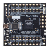
Lattice MachXO3D Breakout Board User Manual (39 pages)
Brand:
Lattice
| Category:
Motherboard
| Size: 2 MB
Table of Contents
Table of Contents
3
Acronyms in this Document
5
1 Introduction
6
2 Features
7
Figure 2.1. Machxo3D Breakout Board, Top Side
7
Figure 2.2. Machxo3D Breakout Board, Bottom Side
8
3 Storage and Handling
9
4 Software Requirements
10
5 Machxo3D Device
11
6 Demonstration Design
12
Running the Demonstration Design
12
Figure 6.1.Demonstration Design Block Diagram
12
Table 6.1. DIP Switch Setting and LED Behavior
12
Download Demo Designs
13
Programming a Demo Design with the Lattice Diamond Programmer
14
Overview
15
Figure 7.1. Machxo3D-9400HC Block Diagram
15
Subsystems
16
Clock Sources
16
Expansion Header Landings
16
Table 7.1. Machxo3D Breakout Board Components and Interfaces
16
Table 7.2. Expansion Connector Reference
16
Table 7.3. Expansion Header Pin Information for Bank 0 (J3)
17
Table 7.4. Expansion Header Pin Information for Bank 1 (J4)
18
Table 7.5. Expansion Header Pin Information for Bank 2 (J6)
19
Table 7.6. Expansion Header Pin Information for Bank 3/4/5 (J8)
20
Figure 7.2. J3/J4 Header Landing Callout
21
Figure 7.3. J6/J8 Header Landing Callout
21
Machxo3D FPGA
22
Programming Interface Circuits
22
Figure 7.4. J1 Header Landing and LED Array Callout
22
Table 7.7. Machxo3D FPGA Interface Reference
22
Table 7.8. USB/JTAG Interface Reference
22
Table 7.9. JTAG Programming Pin Information
22
Leds
23
Power Supply
23
Test Points
23
USB Programming and Debug Interface
23
Table 7.10. SPI Programming Pin Information
23
Table 7.11. I2 Programming Pin Information
23
Table 7.12. Power and User Leds Reference
23
Table 7.13. USB Interface Reference
23
Board Modifications
24
Bypassing the USB Programming Interface
24
Applying External Power
24
Measuring Bank and Core Power
24
Mechanical Specifications
24
Environmental Requirements
24
8 Troubleshooting
25
Leds Do Not Flash
25
USB Cable Not Detected
25
Determine the Source of a Pre-Programmed Device
25
9 Ordering Information
26
Schematics
27
Figure A.1. Block Diagram
27
Figure A.2. USB to JTAG Interface
28
Figure A.3. Power Regulators
29
Figure A.4. Bank0 I/O
30
Figure A.5. Bank1 I/O
31
Figure A.6. Bank2 I/O
32
Figure A.7. Bank3, 4, 5 I/O
33
Figure A.8. Power Decoupling and Leds
34
Bill of Materials
35
Table B.1. Machxo3D Breakout Board Bill of Materials
35
References
37
Lattice Semiconductor Documents
37
Revision History
38
Advertisement
Advertisement
Related Products
Lattice MachXO2280
Lattice MIPI D-PHY
Lattice Certus-NX
Lattice CertusPro-NX Versa Board
Lattice CrossLink LIF-MD6000 Master Link Board - Revision C
Lattice DisplayPort VIP Input Board
Lattice iCE40 Ultra
Lattice iCE40 UltraPlus
Lattice iCE40 UltraPlus 8:1 Mic Aggregation Demo
Lattice Categories
Motherboard
Microcontrollers
Computer Hardware
Network Hardware
Server
More Lattice Manuals
Login
Sign In
OR
Sign in with Facebook
Sign in with Google
Upload manual
Upload from disk
Upload from URL