Sign In
Upload
Manuals
Brands
Lake Shore Manuals
Laboratory Equipment
370
Lake Shore 370 Manuals
Manuals and User Guides for Lake Shore 370. We have
1
Lake Shore 370 manual available for free PDF download: User Manual
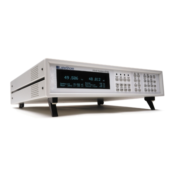
Lake Shore 370 User Manual (184 pages)
AC Resistance Bridge
Brand:
Lake Shore
| Category:
Laboratory Equipment
| Size: 5 MB
Table of Contents
Table of Contents
5
Figure No.
11
Chapter/Paragraph
11
Introduction
11
General
11
Model 370 Front Panel
11
Description
12
Sensor Performance
15
Specifications
19
Safety Summary
21
Safety Symbols
21
Background
23
General
23
Useful Temperature Range
23
Temperature Scales
23
Cryogenic Cooling System Terminology
23
Dilution Refrigerator Terminology
24
Dilution Refrigerator Block Diagram
24
He Cryostat
25
He Cryostat Block Diagram
25
Adiabatic Demagnetization Refrigerator (ADR)
26
Single-Stage ADR Block Diagram
26
Model 370 Theory of Operation
27
Why Is the Model 370 Called a Bridge
27
Resistance Measurement
27
Excitation Modes
28
Resistance Ranges
28
Measurement Circuit
28
Shielding and Grounding Theory
29
Shields
29
Electrical Isolation
29
Driven Guards
29
Active Common Mode Reduction
30
Matched Impedance Current Source
30
Measurement Speed and Filtering
30
Noise Sources
31
Induced Electrical Noise
31
Ground Loop Noise
31
Analog Circuit Noise
31
Digital Circuit Noise
31
Resistor Thermal Noise
32
Interference between Two Model 370S
32
Vibration Noise
32
Measurement Error
32
Warm up and Temperature Drift
32
Resistor Installation
32
Resistor Self-Heating and Thermal Resistance
33
Lead Resistance
33
Current Leakage
33
Cable Capacitance
33
Instrument Operation
34
Operating Tradeoffs
34
Resistor Self-Heating Vs. Excitation
34
Excitation Vs. Signal-To-Noise
35
Signal-To-Noise Vs. Measurement Bandwidth
35
MODEL 3716/L and 3708 SCANNER
35
Scanner Performance
36
Controlling Temperature While Scanning
36
Temperature Measurement
36
Sensor Selection
36
Sensitivity
36
Temperature Range
37
Temperature Resolution
37
Accuracy
37
Packaging
37
Environment
37
Sensor Calibration
38
Sensor Installation
38
Mounting Materials
38
Sensor Location
38
Thermal Conductivity
38
Contact Area
39
Contact Pressure
39
Lead Wire
39
Lead Soldering
39
Heat Sinking Leads
39
Thermal Radiation
39
2.10 Temperature Control
39
2.10.1 Considerations for Good Control
40
Thermal Conductivity
40
Thermal Lag
40
Two-Sensor Approach
40
Thermal Mass
40
System Nonlinearity
40
Closed Loop PID Control
41
Proportional (P)
41
Integral (I)
41
Derivative (D)
41
Manual Output
41
Chapter/Paragraph
36
Examples of PID Control
42
Tuning a Closed Loop PID Controller
43
Setting Heater Range
43
Tuning Proportional
43
Tuning Integral
44
Tuning Derivative
44
Installation
45
General
45
Inspection and Unpacking
45
Rear Panel Definition
46
Model 370 Rear Panel
46
Line Input Assembly
47
Line Voltage
47
Line Fuse and Fuse Holder
47
Power Cord
47
Power Switch
47
Resistor Input Connection and Cabling
48
Resistor Input Connector Definition
48
Shielding and Twisting
48
Resistance Input Connectors
48
Twisted Shielded Cables
48
Driven Guards
49
Isolation and Grounding
49
Guarded Shielded Cables
49
Dressing Cables
50
Example of Instrument Grounding
50
Temperature Sensors
51
Grounding the Scanner
51
Scanner Resistor Input Connector Definition
51
Scanner Resistor Input Cabling
51
Model 3716 Scanner Front and Rear Panels
51
Scanner Output Connector Definition
52
Scanner Output Cabling
52
Scanner Control Connector Definition
54
Scanner Control Cabling
54
Using the Scan Control Signals Without a Scanner
54
Scanner Mounting Bracket
55
Chapter/Paragraph
52
SCAN CONTROL Signals Without a Scanner
55
Monitor and Reference Outputs
56
Monitor Voltage Output
56
Reference Voltage Output
56
Control Heater Output
56
Heater Output Isolation
56
Monitor and Reference Connectors
56
Control Heater Output Connector
56
Heater Output Connection
57
Heater Output Cabling
57
Calculating Control Heater Power
57
Heater Output Protection
57
Boosting Heater Power above 1W
58
Analog Output and Still Heater Output
58
Analog Output Connections
58
Calculating Still Heater Power
58
Calculating Still Heater Current
58
Analog Output Connectors
58
Relay Connection
59
3.10 Rack Mounting
59
Alarm Relays Terminal Block
59
Model RM-1 Rack Mount Kit Assembly
59
Operation
61
General
61
Turning Power on
61
Display Definition
61
Model 370 Display
61
Reading Display
62
Display Update Indicator
62
Range, Excitation and Power
62
Display and LED Annunciators
62
Temperature Control Display
63
Kepad Definition
63
Key Descriptions
63
General Keypad Operation
64
Display Setup
64
Display Setup and Units Selection
64
Display Resolution: 6
66
Display Brightness
66
Excitation Modes, Resistance Range, and Autorange
66
Voltage Excitation Mode
67
Current Excitation Mode
68
Turning Excitation off
68
Input Setup
68
Channel Selection
69
Scanner Dwell Time
69
Change Pause Time
69
Selecting a Temperature Response Curve
70
Temperature Coefficient
70
Turning a Channel on or off
70
Instrument Setup
71
Frequency Selection
71
Active Common Mode Reduction
71
Guard Drive
71
Monitor Output Selection
72
Range and Excitation Keys for One or All Channels
72
Channel on or off
72
Manual Scanner Channel Selection
73
Automatic Scanning
73
Settings for Multiple Channels
73
Firmware Filter
73
4.10 Temperature Measurement
75
Curve Selection
75
Temperature Display
75
4.11 Temperature Control
75
Temperature Control Modes
75
Control Setup
76
Setting Control Mode
76
Control Channel: 1
76
Setpoint Units
77
Setpoint Change Pause Time
77
Control Filter
77
Heater Output Display
78
Heater Resistance: 100.00
78
Heater Range Limit
78
Heater Polarity
79
Changing Setpoint
79
Manually Setting PID Values
80
Manually Setting Proportional (P)
80
Manually Setting Integral (I)
80
Manually Setting Derivative (D)
80
Manual Heater Output
81
Heater Output Range and Heater Output off
81
Setpoint Ramp
82
Controlling and Scanning
83
Reading Sequence
83
Settling Time
83
4.12 Max/Min Capture
83
Linear Equation (Δr)
84
4.14 Alarms
86
Chapter/Paragraph
72
Deadband Example
86
4.15 Relays
89
4.16 Analog Outputs
90
4.17 Still Output
92
Unipolar Versus Bipolar Analog Output
92
4.18 Locking the Keypad
93
4.19 Default Parameter Values
93
Advanced Operation
95
General
95
Curve Numbers and Storage
95
Curve Header Parameters
95
Curve Breakpoints
95
Calcurve
96
Front Panel Curve Entry Operations
96
Edit Curve
96
Erase Curve
99
Copy Curve
100
Zone Tuning
101
Entering Zone Parameter Values
101
Using Zone Tuning
104
Record of Zone Settings
105
Chapter/Paragraph
107
Computer Interface Operation
107
General
107
Ieee-488 Interface
107
Changing IEEE-488 Interface Parameters
107
Remote/Local Operation
108
IEEE-488 Command Structure
108
Status Registers
110
Status Byte Register and Service Request Enable Register
110
Standard Event Status Register and Standard Event Status Enable Register
110
IEEE Interface Example Programs
111
IEEE-488 Interface Board Installation for Visual Basic Program
111
DEV 12 Device Template Configuration
112
Visual Basic IEEE-488 Interface Program Setup
113
Program Operation
116
Troubleshooting
116
Serial Interface Overview
117
Changing Baud Rate
117
Physical Connection
117
Hardware Support
118
Character Format
118
Message Strings
119
Message Flow Control
119
Serial Interface Example Programs
119
Visual Basic Serial Interface Program Setup
120
Program Operation
123
Troubleshooting
123
Command Summary
124
Interface Commands
126
Options and Accessories
143
General
143
Models
143
Options
144
Accessories
144
Model 112-374 Cable Assembly
146
Service
147
General
147
Contacting Lake Shore Cryotronics
147
Returning Products to Lake Shore
147
Fuse Drawer
148
Line Voltage Selection
148
Power Fuse Access
148
Fuse Replacement
149
Error Messages
149
Troubleshooting
150
Enclosure Top Removal and Replacement
154
Signal Flow Block Diagram
154
Electrostatic Discharge
155
8.10 Firmware Replacement
155
Location of Important Internal Components
156
8.11 Connector and Cable Definitions
157
SCAN CONTROL Connector Details
157
Resistor Sensor INPUT Connectors
158
REFERENCE and MONITOR Connector Details
158
HEATER OUTPUT Connector Details
158
ANALOG out 1 and 2 (STILL) Connector Details
158
ALARM RELAYS Terminal Block
159
IEEE-488 Rear Panel Connector Details
161
8.12 Model 370 Calibration
162
Appendix A - Glossary of Terminology
173
Appendix B - Temperature Scales
181
Temperature Scale Comparison
181
Appendix C - Handling of Liquid Helium and Nitrogen
183
Typical Cryogenic Storage Dewar
183
Advertisement
Advertisement
Related Products
Lake Shore 321-02
Lake Shore 321-01
Lake Shore 321-04
Lake Shore 350
Lake Shore 335
Lake Shore 372
Lake Shore Categories
Temperature Controller
Measuring Instruments
Power Supply
Controller
Laboratory Equipment
More Lake Shore Manuals
Login
Sign In
OR
Sign in with Facebook
Sign in with Google
Upload manual
Upload from disk
Upload from URL