Sign In
Upload
Manuals
Brands
Lake Shore Manuals
Temperature Controller
335
Lake Shore 335 Manuals
Manuals and User Guides for Lake Shore 335. We have
1
Lake Shore 335 manual available for free PDF download: User Manual
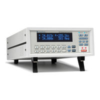
Lake Shore 335 User Manual (170 pages)
Brand:
Lake Shore
| Category:
Temperature Controller
| Size: 11 MB
Table of Contents
Table of Contents
7
Chapter 1 1.1 Product Description
13
Product Description
13
Sensor Inputs
14
Interface
15
Temperature Control
15
Configurable Display
16
Model 3060 Thermocouple Input Option
16
Sensor Selection
17
Model 335 Specifications
19
Input Specifications
19
Sensor Input Configuration
20
Thermometry
20
Control
20
Heater Outputs (Outputs 1 and 2)
20
Front Panel
22
Interface
22
General
22
Safety Summary and Symbols
23
Chapter 2 2.1 General
25
Environmental Conditions
26
Measurement Accuracy
26
Sensor Package
26
Cooling System Design and Temperature Control
25
General
25
Temperature Sensor Selection
25
Temperature Range
25
Sensor Sensitivity
25
Sensor Calibrations
26
Precision Calibration
27
Softcal
27
Sensors Using Standard Curves
27
Curve Handler
27
Sensor Installation
28
Mounting Materials
28
Sensor Location
28
Thermal Conductivity
28
Contact Area
29
Contact Pressure
29
Lead Wire
29
Lead Soldering
30
Thermal Anchoring Leads
30
Thermal Radiation
31
Heater Selection and Installation
31
Heater Resistance and Power
31
Heater Location
32
Heater Types
32
Heater Wiring
33
Consideration for Good Control
33
Thermal Conductivity
33
Thermal Lag
33
Two-Sensor Approach
33
Thermal Mass
34
System Non-Linearity
34
PID Control
34
Proportional (P)
35
Integral (I)
35
Derivative (D)
35
Manual Output
35
Manual Tuning
37
Setting Heater Range
37
Tuning Proportional
37
Tuning Integral
38
Tuning Derivative
39
Autotuning
39
Thermoelectric Devices
40
Zone Tuning
40
Chapter 3 3.1 General
41
General
41
Inspection and Unpacking
41
Line Input Assembly
42
Line Voltage
42
Line Fuse and Fuse Holder
43
Power Cord
43
Power Switch
43
Rear Panel Definition
42
Diode/Resistor Sensor Inputs
43
Sensor Input Connector and Pinout
43
Sensor Lead Cable
44
Grounding and Shielding Sensor Leads
44
Sensor Polarity
45
Four-Lead Sensor Measurement
45
Two-Lead Sensor Measurement
46
Lowering Measurement Noise
46
Thermocouple Sensor Inputs (Thermocouple Model 3060)
47
Sensor Input Terminals
47
Thermocouple Installation
47
Grounding and Shielding
47
Heater Output Setup
48
Heater Output Description
48
Heater Output Connectors
48
Heater Output Wiring
48
Heater Output Noise
49
Powering Output 2 Using an External Power Supply
49
Choosing a Power Supply
49
Connecting to the Model 335
50
Power Supply Setup
50
Programming Voltages under 10 V
51
Chapter 4 4.1 General
53
General
53
Understanding Menu Navigation
53
Front Panel Description
54
Keypad Definitions
54
Direct Operation Keys
54
Menu/Number Pad Keys
54
Annunciators
55
General Keypad Operation
55
Display Setup
56
Display Modes
56
Two Input, One Loop Modes
56
Input Display Modes
57
Two Loop Mode
57
Custom Display Mode
58
Display Brightness
59
Input Setup
59
Diode Sensor Input Setup
60
Positive Temperature Coefficient (PTC) Resistor Sensor Input Setup
60
Negative Temperature Coefficient (NTC) Resistor Sensor Input Setup
60
Range Selection
61
Thermal Electromotive Force (EMF) Compensation
61
Thermocouple Sensor Input Setup (Model 3060 Only)
62
Internal Room Temperature Compensation
62
Internal Room Temperature Compensation Calibration Procedure
62
Curve Selection
63
Filter
64
Input Sensor Name
65
Temperature Limit
65
Preferred Units
66
Max/Min
66
Output and Control Setup
66
Heater Outputs
66
Configuration
67
Heater Output Type (Output 2)
67
Max Current and Heater Resistance
67
User Max Current
68
Power up Enable
69
Closed Loop PID Mode
70
Heater out Display
70
Output Modes
70
Zone Mode 5
70
Control Input
71
Control Parameters
71
Open Loop Mode
71
Integral (I)
72
Proportional (P)
72
Derivative (D)
73
Manual Output
73
Setpoint
74
Setpoint Ramping
75
All off
76
Heater Range
76
Voltage Output
76
Monitor out
77
Warm up Supply
77
Chapter 5 5.1 General
79
Bipolar Control
83
Warm up Percentage
84
Monitor Units
85
Alarms and Relays
86
Alarm Latching
87
Relays
88
Curve Numbers and Storage
89
Front Panel Curve Entry Operations
90
Edit a Breakpoint Pair
91
Add a New Breakpoint Pair
92
Erase Curve
93
Softcal™ with Silicon Diode Sensors
94
Softcal™ Accuracy with DT-400 Series Silicon Diode Sensors
95
Softcal™ Accuracy with Platinum Sensors
96
Emulation Modes
97
Unsupported Commands
98
Hardware Differences
99
General
101
Chapter 6 6.1 General
102
Remote/Local Operation
102
Common Commands
103
Status System Overview
104
Status Byte Register
106
Clearing Registers
107
Operation Event Register Set
108
Status System Detail: Status Byte Register and Service Request
109
Service Request Enable Register
110
Using Status Byte Query (*STB?)
111
USB Interface
112
Installing the Driver from Windows® Update in Windows® XP
113
Manually Install the Driver
114
Installing the USB Driver from the Included CD
115
Communication
116
Command Summary
117
Interface Commands
119
Chapter 7 7.1 General
139
Rack Mounting
141
Model 3060-H Thermocouple Input Option
142
Chapter 8 8.1 General
143
IEEE Interface Troubleshooting
144
Fuse Replacement
145
Factory Reset Menu
146
Product Information
147
Rear Panel Connector Definition
148
IEEE-488 Interface Connector
150
Electrostatic Discharge
151
Firmware Updates
153
Technical Inquiries
154
Shipping Charges
155
Advertisement
Advertisement
Related Products
Lake Shore 321-02
Lake Shore 321-01
Lake Shore 321-04
Lake Shore 350
Lake Shore 372
Lake Shore 370
Lake Shore 218
Lake Shore 218E
Lake Shore 218S
Lake Shore 805
Lake Shore Categories
Temperature Controller
Measuring Instruments
Power Supply
Controller
Laboratory Equipment
More Lake Shore Manuals
Login
Sign In
OR
Sign in with Facebook
Sign in with Google
Upload manual
Upload from disk
Upload from URL