Table of Contents
Advertisement
Quick Links
Model 370S/L/U – AC Resistance Bridge with Model 3716/L 16-Channel Scanners and 3708 8-Channel Preamp
Methods and apparatus disclosed and described herein have been developed solely on company funds of Lake Shore Cryotronics, Inc. No government
or other contractual support or relationship whatsoever has existed which in any way affects or mitigates proprietary rights of Lake Shore Cryotronics,
Inc. in these developments. Methods and apparatus disclosed herein may be subject to U.S. Patents existing or applied for. Lake Shore Cryotronics,
Inc. reserves the right to add, improve, modify, or withdraw functions, design modifications, or products at any time without notice. Lake Shore shall
not be liable for errors contained herein or for incidental or consequential damages in connection with furnishing, performance, or use of this material.
Revision: 1.14
User's Manual
Model 370
AC Resistance Bridge
Includes Coverage For:
Model 370N – AC Resistance Bridge Only
Lake Shore Cryotronics, Inc.
575 McCorkle Blvd.
Westerville, Ohio 43082-8888 USA
E-mail Addresses:
sales@lakeshore.com
service@lakeshore.com
Visit Our Website At:
www.lakeshore.com
Fax: (614) 891-1392
Telephone: (614) 891-2243
P/N 119-033
14 May 2009
Advertisement
Table of Contents
Troubleshooting

Subscribe to Our Youtube Channel
Summary of Contents for Lake Shore 370
- Page 1 Inc. in these developments. Methods and apparatus disclosed herein may be subject to U.S. Patents existing or applied for. Lake Shore Cryotronics, Inc. reserves the right to add, improve, modify, or withdraw functions, design modifications, or products at any time without notice. Lake Shore shall not be liable for errors contained herein or for incidental or consequential damages in connection with furnishing, performance, or use of this material.
- Page 2 Copyright © 2001 – 2009 by Lake Shore Cryotronics, Inc. All rights reserved. No portion of this manual may be reproduced, stored in a retrieval system, or transmitted, in any form or by any means, electronic, mechanical,...
- Page 3 Lake Shore Model 370 AC Resistance Bridge User’s Manual DECLARATION OF CONFORMITY Lake Shore Cryotronics, Inc. 575 McCorkle Blvd. Westerville OH 43082-8888 USA hereby declare that the equipment specified conforms to the following Directives and Standards: Application of Council Directives: ............
- Page 4 To qualify for the CE Mark, the Model 370 meets or exceeds the requirements of the European EMC Directive 89/336/EEC as a CLASS A product. A Class A product is allowed to radiate more RF than a Class B product...
-
Page 5: Table Of Contents
He Cryostat ........................... 2-3 2.3.3 Adiabatic Demagnetization Refrigerator (ADR) ................2-4 MODEL 370 THEORY OF OPERATION ................... 2-5 2.4.1 Why is the Model 370 called a Bridge? ..................2-5 2.4.2 Resistance Measurement ......................2-5 2.4.3 Excitation Modes ..........................2-6 2.4.4 Resistance Ranges ........................ - Page 6 Lake Shore Model 370 AC Resistance Bridge User’s Manual TABLE OF CONTENTS (Continued) Chapter/Paragraph Title Page 2.9.1.1 Sensitivity ..........................2-14 2.9.1.2 Temperature Range ......................... 2-15 2.9.1.3 Temperature Resolution ......................2-15 2.9.1.4 Accuracy ........................... 2-15 2.9.1.5 Packaging ..........................2-15 2.9.1.6 Environment ..........................2-15 2.9.2...
- Page 7 Lake Shore Model 370 AC Resistance Bridge User’s Manual TABLE OF CONTENTS (Continued) Chapter/Paragraph Title Page 3.5.4 Scanner Output Connector Definition .................... 3-8 3.5.5 Scanner Output Cabling ......................... 3-9 3.5.6 Scanner Control Connector Definition ..................3-10 3.5.7 Scanner Control Cabling ......................3-10 3.5.8...
- Page 8 Lake Shore Model 370 AC Resistance Bridge User’s Manual TABLE OF CONTENTS (Continued) Chapter/Paragraph Title Page 4.7.5 Range and Excitation Keys for One or All Channels ..............4-12 MODEL 3716 SCANNER OPERATION ..................4-12 4.8.1 Channel On or Off ........................4-12 4.8.2...
- Page 9 Lake Shore Model 370 AC Resistance Bridge User’s Manual TABLE OF CONTENTS (Continued) Chapter/Paragraph Title Page COMPUTER INTERFACE OPERATION ........................ 6-1 GENERAL ............................6-1 IEEE-488 INTERFACE ........................6-1 6.1.1 Changing IEEE-488 Interface Parameters ..................6-1 6.1.2 Remote/Local Operation ........................ 6-2 6.1.3...
- Page 10 Lake Shore Model 370 AC Resistance Bridge User’s Manual LIST OF ILLUSTRATIONS Figure No. Title Page Model 370 Front Panel ............................... 1-1 Dilution Refrigerator Block Diagram ........................... 2-2 He Cryostat Block Diagram ............................... 2-3 Single-Stage ADR Block Diagram ............................2-4 Examples of PID Control ..............................
-
Page 11: Introduction
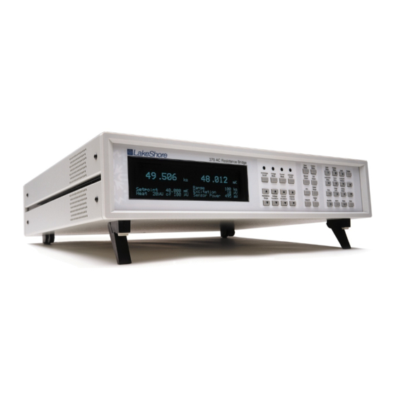
This chapter provides an introduction to the Model 370 AC Resistance Bridge. The Model 370 was designed and manufactured in the United States of America by Lake Shore Cryotronics, Inc. The Model 370 features include the following. Model 370 Features •... -
Page 12: Description
For applications where lead length is greater than 10 ft, or resistance is greater than 100 kΩ, the Model 370 also includes four separate driven guards that follow the voltage on each lead to provide the lowest possible voltage difference between the lead and its shield. - Page 13 Autorange and Manual Range The Model 370 autorange and manual range selection functions of the Model 370 are available for use with both current excitation mode and voltage mode. The autorange function increases or decreases the resistance range when measured resistance exceeds or falls below the range in use.
- Page 14 The Model 3716 Scanner The Model 3716 mirrors the single input of the Model 370 that is optimized for low residual DC bias current. Low bias provides the lowest available resistor self-heating when excitation currents are in the range of 1 pA to 30 pA. It also provides the best available accuracy when resistances are above 200 kΩ.
-
Page 15: Sensor Performance
Lake Shore Model 370 AC Resistance Bridge User’s Manual SENSOR PERFORMANCE Lake Shore Germanium GR-200A-30 Sensor Properties Excitation and Instrumentation Temperature Resistance dR/dT Thermal Resistance Excitation Excitation Power Resistance Range Voltage Limit Current 0.05 200 mK/nW 63.2 µV 1 nA 25 fW 25 kΩ... - Page 16 Lake Shore Model 370 AC Resistance Bridge User’s Manual Accuracy: ±0.03% ±0.05% ±0.1% ±0.3% Table 1-1. Model 370/3716 Voltage Range 632 mV 200 mV 63.2 mV 20 mV 6.32 mV 2.0 mV 632 µV 200 µV 63.2 µV 20 µV 6.32 µV...
- Page 17 Lake Shore Model 370 AC Resistance Bridge User’s Manual Accuracy: ±0.03% ±0.05% ±0.1% ±0.3% Table 1-2. Model 370/3716L Voltage Range 632 mV 200 mV 63.2 mV 20 mV 6.32 mV 2.0 mV 632 µV 200 µV 63.2 µV 20 µV 6.32 µV...
- Page 18 Lake Shore Model 370 AC Resistance Bridge User’s Manual Table 1-3. Model 370/3708 Voltage Range Accuracy: ±0.03% ±0.05% ±0.1% ±0.3% 6.32 mV 2.0 mV 632 µV 200 µV 63.2 µV 20 µV 6.32 µV 2.0 µV 200 mΩ 63.2 mΩ...
-
Page 19: Specifications
Lake Shore Model 370 AC Resistance Bridge User’s Manual SPECIFICATIONS Measurement Type: AC, 4-lead differential, resistance Temperature Control Number of Inputs: 1; 16 with Model 3716 Scanner Control Type: High resolution digital PID Measurement Units: Ohms, Kelvin (with temperature response curve) Control Modes: Closed Loop PID, Open Loop Resistance Ranges: 2 mΩ... - Page 20 CAL-370-CERT – Instrument recalibration with certificate Approval: CE mark (consult factory for availability) CAL-370-DATA – Instrument recalibration with certificate and data RM-1 – Kit for mounting one Model 370 in a 482.6 mm (19 in) rack 3716/L and 3708 Scanners mount cabinet Size: 135 mm W x 66 mm H x 157 mm D (5.2 in x 2.6 in x 6.2 in)
-
Page 21: Safety Summary
Observe these general safety precautions during all phases of instrument operation, service, and repair. Failure to comply with these precautions or with specific warnings elsewhere in this manual violates safety standards of design, manufacture, and intended instrument use. Lake Shore Cryotronics, Inc. assumes no liability for Customer failure to comply with these requirements. - Page 22 Lake Shore Model 370 AC Resistance Bridge User’s Manual This Page Intentionally Left Blank 1-12 Introduction...
-
Page 23: Background
100 mK in a capable cryogenic cooling system. With careful installation of a high quality bridge like the Model 370 it is not difficult to achieve 50 mK. Below that, each detail of the overall system has to be optimized to a low end of between 10 and 20 mK. -
Page 24: Dilution Refrigerator Terminology
Lake Shore Model 370 AC Resistance Bridge User’s Manual 2.3.1 Dilution Refrigerator Terminology Dilution refrigerators remain the workhorse of low temperature research down to approximately 5 – 10 mK. So many variations of factory and home built units exist that it is unlikely that any two are identical. Figure 2-1 illustrates only the most basic features. -
Page 25: He Cryostat
Lake Shore Model 370 AC Resistance Bridge User’s Manual 2.3.2 He Cryostat He Cryostats are the least complex systems capable of reaching temperatures down to 300 mK. Even at such relatively warm temperatures the benefits of a well designed resistance bridge must be considered when selecting instrumentation. -
Page 26: Adiabatic Demagnetization Refrigerator (Adr)
There has recently been growing interest in the technology and it is finding its way into many new applications. The Model 370 has many features that can help automate and control these systems in temperature ranges where leaded resistance measurement is practical. Figure 2-3 illustrates a typical first stage of an ADR but other stages can be added. -
Page 27: Model 370 Theory Of Operation
The Model 370 uses current excitation because controlled current is very stable and predictable. Current can also be scaled easily, which is necessary to achieve low excitation. The Model 370 has 21 current settings down to 3.16 pA. These currents have low noise and almost no DC component to self heat the measured resistor. Two excitation modes are available to best utilize the features of the current source in different applications. -
Page 28: Excitation Modes
Most parts of a good strategy are obvious, some are not and even the best plans do not work all the time. The Model 370 offers several features that help control noise and maintain signal integrity. -
Page 29: Shielding And Grounding Theory
Guards are not necessary when measured resistance is low or cable capacitance is low. The guards on the Model 370 can be turned on or off by the user as required by the application. Cables between the instrument and cryostat can be guarded even if it is impractical to continue guarding inside the cryostat. -
Page 30: Active Common Mode Reduction
Matched Impedance Current Source The Model 370 takes the idea of a differential input one step further with a unique feature in its current source. The two current source output terminals have the same source impedance, similar to the voltage input terminals of a differential input that have the same input impedance. -
Page 31: Noise Sources
Leakage current limits the practical current excitation range of the Model 370 to a few picoamps. Most analog circuit noise is distributed over a broad frequency band. It is often referred to as 1/f noise because there is equal noise power in each decade of frequency. -
Page 32: Resistor Thermal Noise
Warm Up and Temperature Drift When the Model 370 is first turned on it should be allowed to warm up for at least 30 minutes before use to allow its internal temperature to stabilize. Warm up is an exaggerated form of temperature drift because the temperature change inside the enclosure is larger and faster than would be experienced in a laboratory setting. -
Page 33: Resistor Self-Heating And Thermal Resistance
Cable capacitance and measured resistance act together as a low-pass filter to attenuate the desired measurement signal and shift its phase. Low excitation frequency was chosen for the Model 370 to minimize this effect but capacitance can still contribute to measurement error when resistance is high. Driven guards should be used when measuring resistance above 100 kΩ... -
Page 34: Instrument Operation
If noise is not suspected as a potential problem, it is may be easier to measure the effect of self-heating using the many current ranges available in the Model 370 than try to calculate thermal resistance. Begin by cooling the resistor to the desired temperature and measure its value using current excitation and select a current in the middle of the available choices. -
Page 35: Excitation Vs. Signal-To-Noise
Refer to Paragraph 3.5 for scanner installation. The Model 370 can read any of the 16 scanner channels, one at a time. Channel change can be done manually or with the autoscan feature. The instrument stores input setup information for each channel and will use the appropriate setup for each channel when selected. -
Page 36: Scanner Performance
Proper installation combined with the noise reduction features built into both the Model 370 and Model 3716/L and 3708 can minimize the effects but a full loaded scanner may never be as quiet as a single guarded and shielded resistance input. A measurable increase in noise is most likely when measuring large resistance of more than 100 kΩ. -
Page 37: Temperature Range
50 mK to 83 μK at 1 K. The reason that the drop in resolution is not as severe as the drop in sensitivity is that excitation current is increased approximately 1,000 times by the Model 370 to maintain practical measurement parameters. -
Page 38: Sensor Calibration
Sensor Calibration The Model 370 can convert the resistance of a sensor to temperature if a temperature response curve is loaded into the instrument. Most curves are generated from an individual sensor calibration because few sensors follow a standard curve at low temperatures. -
Page 39: Contact Area
2.10 TEMPERATURE CONTROL The Model 370 includes the necessary electronics to perform closed-loop temperature control in a dilution refrigerator or other low power cryogenic cooling system. The load must be equipped with a temperature sensor for feedback and a resistive heater to add heating power into the system. -
Page 40: 2.10.1 Considerations For Good Control
Lake Shore Model 370 AC Resistance Bridge User’s Manual 2.10.1 Considerations For Good Control Most of the techniques discussed above to improve cryogenic temperature measurement apply to control as well. There is an obvious exception in sensor location and a compromise is suggested in Paragraph 2.10.3. -
Page 41: Closed Loop Pid Control
Manual Output The Model 370 has a control parameter that is not a normal part of a PID control loop. Manual output can be used for open loop control, meaning feedback is ignored and the heater output stays at the users manual setting. This is a good way to put constant heating power into a load when needed. -
Page 42: Examples Of Pid Control
Lake Shore Model 370 AC Resistance Bridge User’s Manual PID Control.bmp Figure 2-4. Examples of PID Control 2-20 Theory of Operation... -
Page 43: Tuning A Closed Loop Pid Controller
Begin this part of the tuning process by letting the cooling system cool and stabilize with the heater off. Place the Model 370 in closed loop PID control mode, then turn integral, derivative and manual output settings off. Enter a setpoint above the cooling systems lowest temperature. -
Page 44: Tuning Integral
See Figure 2-4(e). A derivative setting of zero, off, is recommended when the control system is seldom changed and data is taken when the load is at steady state. The derivative setting is entered into the Model 370 in seconds and a good starting point is one fourth the integral setting in seconds. -
Page 45: Installation
Check off each item on the packing list as it is unpacked. Instruments themselves may be shipped as several parts. The items included with the Model 370 and optional scanners are listed below. Contact Lake Shore immediately if there is a shortage of parts or accessories. -
Page 46: Rear Panel Definition
REAR PANEL DEFINITION This paragraph defines the rear panel of the Model 370. See Figure 3-1. Readers are referred to paragraphs that contain installation instructions and connector pin-outs for each feature. Definition of the Model 3716 Scanner is given in Paragraph 3.5. -
Page 47: Line Input Assembly
Line Fuse and Fuse Holder The line fuse is an important safety feature of the Model 370. If a fuse ever fails, it is important to replace it with the value and type indicated on the rear panel for the line voltage setting. The letter T on the fuse rating indicates that the instrument requires a time-delay or slow-blow fuse. -
Page 48: Resistor Input Connection And Cabling
Tied to measurement common NOTES: 1. The Model 370 makes an AC resistance measurement therefore the + and – signs are to aid in proper lead arrangement and not indicate signal polarity. 2. Active guards can be turned on or off by the user. In the off state the guard pins default to signal common but do not substitute for shields. -
Page 49: Driven Guards
(Obviously this will not shield noise generated within the Dewar.) In many installations the best noise performance of the Model 370 can be achieved when the cable shield is tied directly to the Dewar or other large conductive mass surrounding the experimental space. The problem is that most test Dewars are connected to Earth ground either directly or through the many vacuum and transfer lines running in and out. -
Page 50: Dressing Cables
Isolation and Grounding (Continued) Any additional connection between measurement circuits and ground will defeat the isolation built into the Model 370 and allow ground loops to form. In the unusual circumstance that one measurement lead is shorted to the cable shield (measurement common) the Model 370 can still make resistance measurements but the active CMR feature must be turned off. -
Page 51: Temperature Sensors
The Model 3716/L and 3708 Scanners expands the input capability of the Model 370 and increase the number of input channels to 16 (3716/L) or 8 (3708). It is an extension of the isolated measurement circuitry of the Model 370 so its installation should follow the guidelines described in Paragraph 3.4 as well as this paragraph. -
Page 52: Scanner Output Connector Definition
Two 6-pin (240°) Circular DIN 45322 receptacles are used for the resistance measurement output from the scanner. These are identical to the connectors used on the resistance input of the Model 370. The cables included with the scanner are adequate for most installations. Connector pin definition on the scanner is identical to the input connector definition given in Paragraph 3.4.1 in case a cable must be made for a special application. - Page 53 Lake Shore Model 370 AC Resistance Bridge User’s Manual 112-374a.bmp Cable Wiring.bmp Figure 3-9. Scanner to Instrument Measurement Cable Installation...
-
Page 54: Scanner Control Connector Definition
Lake Shore Model 370 AC Resistance Bridge User’s Manual 3.5.6 Scanner Control Connector Definition A 15-pin D subminiature plug provides power supply and digital control input connections to the Model 3716/L and 3708 Scanner. The scanner control cable included with the scanner is adequate for most installations. A connector pin definition is provided in case a cable must be made for a special application. -
Page 55: Scanner Mounting Bracket
Lake Shore Model 370 AC Resistance Bridge User’s Manual Scan Control.bmp Name Description Name Description Digital Common Common or ground +5 V Scan 2 TTL Digital Output 2 Digital Common Scan 3 TTL Digital Output 3 Analog Common Common or ground for ±15 V... -
Page 56: Monitor And Reference Outputs
Lake Shore Model 370 AC Resistance Bridge User’s Manual MONITOR AND REFERENCE OUTPUTS The monitor and reference voltage outputs are included to aid in troubleshooting especially identification of ground loops and other noise sources during instrument installation. Both signal outputs and their common connections are part of the isolated measurement circuitry and should be treated like part of the resistance measurement. -
Page 57: Heater Output Connection
The heater output hardware is internally protected against open circuit and short circuit conditions. The output should never be connected to an external power source. There are additional firmware features in the Model 370 to help prevent damage to the load. The heater will automatically turn itself off if an open circuit condition is detected. The instrument will not allow the control setpoint to be larger than the setpoint temperature limit stored with the temperature response curve. -
Page 58: Boosting Heater Power Above 1W
Boosting Heater Power Above 1W An external power supply can be used to boost the power output of a Model 370 if a temperature control application requires more than the 1 W of heater power. The control heater output can be used to program a voltage programmable DC power supply of almost any size. -
Page 59: Relay Connection
(NO), common (COM) and normally closed (NC) contact for a total of 6. All of these connections are electrically isolated from all other circuits in the Model 370. The relay is in its normal state when it is Off and in its active state when it is On. - Page 60 Lake Shore Model 370 AC Resistance Bridge User’s Manual This Page Intentionally Left Blank 3-16 Installation...
-
Page 61: Operation
Paragraph 3.3.1. When the Model 370 is turned on the display shows the Lake Shore logo for a few seconds and the alarm beeper sounds briefly to indicate the instrument is initializing itself. Most of the instrument setup parameter values are retained when power is off with a few exceptions. -
Page 62: Reading Display
90% and off 10% when the instrument is reporting stable readings and all features are active. If a Model 3716 Scanner is attached to the Model 370 the channel indicators take the place of the display update indicator. -
Page 63: Temperature Control Display
KEYPAD DEFINITION The Model 370 has 36 keys separated into 3 groups on the instrument front panel. The group of keys closest to the display act directly on the resistance measurement, the center group contains temperature control features and the far right group combines instrument setup and data entry. -
Page 64: General Keypad Operation
Escape before pressing an arrow or number key. Changes “entered” before Escape is pressed are kept. DISPLAY SETUP The display setup sequence for the Model 370 may seem complicated at first but the steps are necessary to provide flexibility to the operator. 4.4.1 Display Setup and Units Selection Display setup begins with choosing the number of reading locations on the display. - Page 65 Lake Shore Model 370 AC Resistance Bridge User’s Manual Display Setup and Units Selection (Continued) To configure the display press Display Setup. The first display setup screen appears as a prompt for the number of reading locations. Display Setup Select With °®...
-
Page 66: Display Resolution: 6
Display Brightness The vacuum fluorescent (VF) display on the Model 370 has four brightness settings between 100% and 25% that can be changed from the front panel. The brightness setting changes the entire VF display but does not affect the LED annunciators to the right of the display. -
Page 67: Voltage Excitation Mode
Lake Shore Model 370 AC Resistance Bridge User’s Manual 4.5.1 Voltage Excitation Mode In voltage excitation mode the excitation selection in volts is treated as a not to exceed value. The instrument assigns an excitation current to each resistance range that keeps the measurement voltage is as large as possible without exceeding the selected excitation voltage. -
Page 68: Current Excitation Mode
Turning Excitation Off The Model 370 offers many excitation levels with the lowest being very low in power. It is still sometimes necessary to turn excitation off. Excitation should be turned off any time the current source leads are open circuited and then attached to a cold resistor with the instrument turned on. -
Page 69: Channel Selection
Lake Shore Model 370 AC Resistance Bridge User’s Manual 4.6.1 Channel Selection To begin input setup press the Input Setup key. If a scanner is installed, the first input setup screen appears as a prompt for the channel number. All of the parameter changes that follow will act on the selected channel. If no scanner is installed, the sequence will begin below with change pause. -
Page 70: Selecting A Temperature Response Curve
Refer to Paragraph 5.2.1 for information on how to enter curves into the Model 370. If a curve is selected for a channel, the temperature coefficient (used for temperature control) is taken from that curve and the temperature coefficient parameter below is ignored. -
Page 71: Instrument Setup
Active Common Mode Reduction Active common mode reduction is a special feature of the Model 370 that can reduce noise on measurement leads. It is most useful when excitation current is 1 μA or greater but should be left on unless one resistor lead is shorted to measurement common, refer to Paragraph 3.4. -
Page 72: Monitor Output Selection
Monitor Output Selection The monitor output on the Model 370 is a tool to help the user diagnose measurement problems. The output can be set to monitor test voltages from several points inside the instrument. The monitor voltages are often used with the reference output. -
Page 73: Manual Scanner Channel Selection
The Model 370 also allows the user to make changes to the input parameters for all channels. All channels can be selected for parameters under the Input Setup key by selecting the channel designator “All”. - Page 74 Filter settling time begins after the pause time finishes on range or channel change. Because the Model 370 uses a linear average the measurement bandwidth is not a simple function of frequency.
-
Page 75: 4.10 Temperature Measurement
The Model 370 offers two tuning modes or ways to set the necessary P, I, and D parameters for closed loop control. In closed loop PID mode the control parameter values are set manually as described in Paragraph 2.10. Once appropriate parameters are found they can be stored in the instrument and recalled with the zone feature. -
Page 76: Control Setup
Lake Shore Model 370 AC Resistance Bridge User’s Manual 4.11.2 Control Setup Several control parameters are grouped under the Control Setup key. These are considered setup parameters because they are normally set when configuring the control loop and not used often during operation. Control parameters that change often are assigned their own keys. -
Page 77: Setpoint Units
Lake Shore Model 370 AC Resistance Bridge User’s Manual 4.11.2.3 Setpoint Units Closed-loop temperature control will operate with a setpoint in resistance units for any input channel and a setpoint in Kelvin for any channel that has a temperature response curve assigned to it. Setpoint units will default to ohms if no curve is selected for the control channel. -
Page 78: Heater Output Display
The heater output or control output is a variable DC current source with several ranges to accommodate different loads. The Model 370 can be configured to display the output range as its full scale current and the output as a percent of that current. -
Page 79: Heater Polarity
Lake Shore Model 370 AC Resistance Bridge User’s Manual 4.11.2.9 Heater Polarity When the heater output is used in a traditional manner, to drive a resistive load, the heater output needs to be unipolar since reversing the current will still heat the load. There may be some rare circumstances when the heater output is not connected to a resistive load and bipolar control is desired. -
Page 80: Manually Setting Pid Values
Manually Setting PID Values When operating the Model 370 as a temperature controller in closed loop PID mode, proportional (P), integral (I) and derivative (D) parameter values must be properly selected to tune the control loop. Chapter 2 of this manual describes the principals of closed loop (feedback) control including some tuning suggestions. -
Page 81: Manual Heater Output
Lake Shore Model 370 AC Resistance Bridge User’s Manual 4.11.5 Manual Heater Output Manual heater output is most often used during open loop control but it is also active during closed loop PID control. Operation of the parameter is different during the two control modes. During open loop control the instrument uses the manual output value to calculate the heater output on a given heater range. -
Page 82: Setpoint Ramp
Setpoint Ramp The Model 370 can be configured to ramp the control setpoint from its present value to a new value. The ramp can produce a smooth, linear transition in temperature rather than the step response normally associated with closed loop PID control. -
Page 83: Controlling And Scanning
Controlling and Scanning The Model 370 and 3716 Scanner allow both temperature control and data taking at the same time. Firmware in the Model 370 manages automatic switching between the control channel and scan channel and will maintain the control heater output when the control channel is not active. -
Page 84: Linear Equation (Δr)
4.13 LINEAR EQUATION (ΔR) The Model 370 can scale one source of reading data from each channel with either of two linear equations. Scaled readings can be displayed or sent to the analog voltage output as a control signal. The feature can be configured to calculate an error value, ΔR, or a scaled error value such as 10ΔR. - Page 85 Lake Shore Model 370 AC Resistance Bridge User’s Manual Linear Equation (Continued) The next linear setup screen appears as a prompt for a slope value, M. Linear Setup Channel Enter A Value For Slope (M): 1.0000 Use the data entry keys to enter a slope between 0.001 and 1000. Press Enter to accept the new selection and continue to the next setting screen.
-
Page 86: 4.14 Alarms
4.14 ALARMS The Model 370 can compare reading data from each channel to a high and low alarm setpoint. Alarm setpoints and most other alarm parameters can be set independently for each channel. If the Model 3716 Scanner is installed, the alarm operates for the active scan channel only. - Page 87 Lake Shore Model 370 AC Resistance Bridge User’s Manual Alarms (Continued) To begin alarm setup press the Alarm key and press Enter to skip past the reset screen. If a scanner is installed, the alarm setup screen appears as a prompt for the channel number. All of the parameter changes that follow will act on the selected channel.
- Page 88 Lake Shore Model 370 AC Resistance Bridge User’s Manual Alarms (Continued) The next alarm setup screen appears as a prompt for latching or non-latching. Alarm Setup Channel Select With Alarm: Non-latching Use the s or t key to select latching or non-latching. Press Enter to accept the new selection. If latching is selected, the deadband screen will be skipped.
-
Page 89: 4.15 Relays
4.15 RELAYS The Model 370 has two mechanical relays designated high and low. The relays are most commonly associated with the high and low alarms, but they can also be controlled manually and used for other purposes. Both relays default to their normal state when instrument power is turned off. -
Page 90: 4.16 Analog Outputs
4.16 ANALOG OUTPUTS The Model 370 has two analog voltage outputs designated ANALOG OUT 1 and ANALOG OUT 2 (STILL). They are variable DC voltage sources that can vary from +10 V to –10 V. The voltages are generated from a 16-bit digital to analog converter (DAC) with a resolution of 0.3 mV or 0.003 % of full scale. - Page 91 Lake Shore Model 370 AC Resistance Bridge User’s Manual Analog Outputs (Continued) If manual mode is selected, the next analog output setup screen appears as a prompt for the manual output value. Analog Out Setup Analog Out 1 Enter A Value For Manual Output: +0.0000...
-
Page 92: 4.17 Still Output
4.17 STILL OUTPUT The Model 370 can provide the small amount of power required to drive the still heater of a dilution refrigerator with analog voltage output 2. None of the analog output hardware changes when it is configured for still operation. Paragraph 3.8.3 describes how to estimate the full-scale current sourced to a resistive heater. -
Page 93: 4.18 Locking The Keypad
Lake Shore Model 370 AC Resistance Bridge User’s Manual 4.18 LOCKING THE KEYPAD The keypad lock feature prevents accidental changes to parameter values. When the keypad is locked most parameter values may be viewed but only a few can be changed from the front panel. The temperature control heater can be turned off but not changed in range and latched alarms can be reset when the keypad is locked. - Page 94 Lake Shore Model 370 AC Resistance Bridge User’s Manual Default Parameter Values (Continued) The next screen appears to show the input firmware revision date and as a prompt for clearing user curve memory. Input Code: 1.0 Select With °® Clear Curves: No Use the keys to select Yes to clear curves and No to continue without clearing.
-
Page 95: Advanced Operation
CURVE NUMBERS AND STORAGE The Model 370 has 20 user curve locations numbered 1 thru 20. Each location can hold from 2 to 200 data pairs (breakpoints) including a value in ohms or log ohms and a corresponding temperature value in Kelvin. The curves are stored in nonvolatile memory and retained when power is turned off. -
Page 96: Calcurve
RS-232C or IEEE-488 interface have another option. The Model 8000 is included with the calibrated sensor and can be loaded by the user. Lake Shore offers a free curve loading program that is compatible with Model 8000 CalCurves. - Page 97 Lake Shore Model 370 AC Resistance Bridge User’s Manual Table 5-2. Recommended Curve Parameters Typical Lake Shore Recommended Type Units Format Limit (K) Coefficient Model Resolution Platinum 100 PT-100 Ohms Positive 0.001 ( Ω/K Ω Platinum 1000 PT-100 Ohms Ω/K Positive 0.01 (...
- Page 98 Lake Shore Model 370 AC Resistance Bridge User’s Manual Edit Curve (Continued) The next curve entry screen appears as a prompt for the curve format. Curve Entry Edit Curve Select With °® Curve Format: Log ¦/K Use the s or t key to select a curve format of Ω/K or Log Ω/K. Press Enter to accept the new selection and continue to the next setting screen.
-
Page 99: Erase Curve
3. To delete a breakpoint, enter all zeros for both the resistance and temperature. 4. When curve entry is complete, the user must assign the new curve to an input channel. The Model 370 does not automatically assign the new curve to a channel even if there is only one. -
Page 100: Copy Curve
Copy Curve Temperature curves can be copied from one location inside the Model 370 to another. This is a good way to make small changes to an existing curve. Curve copy may also be necessary if the user needs the same curve with two different temperature limits. -
Page 101: Zone Tuning
Entering Zone Parameter Values The Model 370 allows the user to establish up to 10 custom contiguous temperature zones. The user should configure the zones using zone 1 for the lowest temperature and zone 10 for the highest temperature. Zone boundaries are always specified in Kelvin (K) and the upper limit of each zone acts as the lower limit of the next zone. - Page 102 Lake Shore Model 370 AC Resistance Bridge User’s Manual Entering Zone Parameter Values (Continued) The next zone setup screen appears as a prompt for the integral (I) value. Zone Setup Zone Enter A Value For Integral (I): 20.000 Use the data entry keys to enter an integral value between 1 and 10,000 or zero for off. Press Enter to accept the new selection and continue to the next setting screen.
- Page 103 Lake Shore Model 370 AC Resistance Bridge User’s Manual Entering Zone Parameter Values (Continued) The next zone setup screen appears as a prompt for the low relay setting. This setting is only used if the relay is set to zone mode.
-
Page 104: Using Zone Tuning
Lake Shore Model 370 AC Resistance Bridge User’s Manual 5.3.2 Using Zone Tuning Once all zone parameters have been programmed, the controller must be placed in zone tuning mode. When in zone tuning mode, the instrument will update the control settings each time the setpoint is changed to a new zone. If the settings are changed manually, the controller will use the new setting while it is in the same zone and update to the zone table settings when the setpoint is changed to a value outside that zone. -
Page 105: Record Of Zone Settings
Lake Shore Model 370 AC Resistance Bridge User’s Manual Zone Setting Work Sheet Zone 10 Setpoint: Manual Output Heater High Analog Out1 Analog Out2 (0.1-1k) (0.1-1k) (0-200) (0-100%) Range Relay Relay (0-100%) (0-100%) On/Off On/Off Zone 09 Setpoint: Manual Output... - Page 106 Lake Shore Model 370 AC Resistance Bridge User’s Manual This Page Intentionally Left Blank 5-12 Advanced Operation...
-
Page 107: Computer Interface Operation
(Model 4005) is required to use the IEEE-488 Interface and the ALARM RELAYS terminal block at the same time. Cable lengths are limited to 2 meters for each device and 20 meters for the entire bus. The Model 370 can drive bus with up to 10 loads. -
Page 108: Remote/Local Operation
6.1.2 Remote/Local Operation Normal operations from the keypad are referred to as ‘Local’ operations. The Model 370 can also be configured for ‘Remote’ operations via the IEEE-488 interface or the Local key. The Local key will toggle between ‘Remote’ and ‘Local’... - Page 109 IEEE-488 1987 standard share these commands and their format. Common commands all begin with an asterisk. They generally relate to “bus” and “instrument” status and identification. Common query commands end with a question mark (?). Model 370 common commands are detailed in Paragraph 6.3 and summarized in Table 6-6.
-
Page 110: Status Registers
Ramp Done, Bit (7) – This bit is set when a ramp is completed. Service Request (SRQ) Bit (6) – Determines whether the Model 370 is to report via the SRQ line. If bits 2, 3, 4, 5 and/or 7 are set, then the corresponding bit in the Status Byte Register will be set. The Model 370 will produce a service request only if bit 6 of the Service Request Enable Register is set. -
Page 111: Ieee Interface Example Programs
Operation Complete (OPC), Bit (0) – This bit is generated in response to the QOPC common command. It indicates when the Model 370 has completed all selected pending operations. It is not related to the QOPC? command, which is a separate interface feature. -
Page 112: Dev 12 Device Template Configuration
Lake Shore Model 370 AC Resistance Bridge User’s Manual Figure 6-1. GPIB0 Setting Configuration Figure 6-2. DEV 12 Device Template Configuration Remote Operation... -
Page 113: Visual Basic Ieee-488 Interface Program Setup
Lake Shore Model 370 AC Resistance Bridge User’s Manual 6.1.5.2 Visual Basic IEEE-488 Interface Program Setup This IEEE-488 interface program works with Visual Basic 6.0 (VB6) on an IBM PC (or compatible) with a Pentium- class processor. A Pentium 90 or higher is recommended, running Windows 95 or better. It assumes your IEEE-488 (GPIB) card is installed and operating correctly (refer to Paragraph 6.1.5.1). - Page 114 Lake Shore Model 370 AC Resistance Bridge User’s Manual Table 6-1. IEEE-488 Interface Program Control Properties Current Name Property New Value Label1 Name lblExitProgram Caption Type “exit” to end program. Label2 Name lblCommand Caption Command Label3 Name lblResponse Caption Response...
- Page 115 Lake Shore Model 370 AC Resistance Bridge User’s Manual Table 6-2. Visual Basic IEEE-488 Interface Program Public gSend As Boolean 'Global used for Send button state Private Sub cmdSend_Click() 'Routine to handle Send button press gSend = True 'Set Flag to True...
-
Page 116: Program Operation
Lake Shore Model 370 AC Resistance Bridge User’s Manual 6.1.5.3 Program Operation Once the example program is running, try the following commands and observe the response of the instrument. Input from the user is shown in bold and terminators are added by the program. The word [term] indicates the required terminators included with the response. -
Page 117: Serial Interface Overview
SERIAL INTERFACE OVERVIEW The serial interface used in the Model 370 is commonly referred to as an RS-232C interface. RS-232C is a standard of the Electronics Industries Association (EIA) that describes one of the most common interfaces between computers and electronic equipment. -
Page 118: Hardware Support
Hardware Support The Model 370 interface hardware supports the following features. Asynchronous timing is used for the individual bit data within a character. This timing requires start and stop bits as part of each character so the transmitter and receiver can resynchronized between each character. -
Page 119: Message Strings
Lake Shore Model 370 AC Resistance Bridge User’s Manual Message Strings (Continued) A query string is issued by the computer and instructs the instrument to send a response. The query format is: <query mnemonic><?><space><parameter data><terminators>. Query mnemonics are often the same as commands with the addition of a question mark. Parameter data is often unnecessary when sending queries. -
Page 120: Visual Basic Serial Interface Program Setup
Lake Shore Model 370 AC Resistance Bridge User’s Manual 6.2.7.1 Visual Basic Serial Interface Program Setup The serial interface program works with Visual Basic 6.0 (VB6) on an IBM PC (or compatible) with a Pentium-class processor. A Pentium 90 or higher is recommended, running Windows 95 or better, with a serial interface. It uses the COM1 communications port at 9600 Baud. - Page 121 Lake Shore Model 370 AC Resistance Bridge User’s Manual Table 6-4. Serial Interface Program Control Properties Current Name Property New Value Label1 Name lblExitProgram Caption Type “exit” to end program. Label2 Name lblCommand Caption Command Label3 Name lblResponse Caption Response...
- Page 122 Lake Shore Model 370 AC Resistance Bridge User’s Manual Table 6-5. Visual Basic Serial Interface Program Public gSend As Boolean 'Global used for Send button state Private Sub cmdSend_Click() 'Routine to handle Send button press gSend = True 'Set Flag to True...
-
Page 123: Program Operation
Lake Shore Model 370 AC Resistance Bridge User’s Manual 6.2.7.2 Program Operation Once the example program is running, try the following commands and observe the response of the instrument. Input from the user is shown in bold and terminators are added by the program. The word [term] indicates the required terminators included with the response. -
Page 124: Command Summary
Lake Shore Model 370 AC Resistance Bridge User’s Manual COMMAND SUMMARY This paragraph provides a listing of the IEEE-488 and Serial Interface Commands. A summary of all the commands is provided in Table 6-6. All the commands are detailed in Paragraph 6.3.1, which is presented in alphabetical order. - Page 125 Lake Shore Model 370 AC Resistance Bridge User’s Manual Table 6-6. Command Summary Command Function Page Command Function Page FREQ Excitation Frequency Cmd ........28 Clear Interface Cmd ..........20 FREQ? Excitation Frequency Query ........28 Event Status Enable Cmd ........20 GUARD Guard Drive Cmd ............
-
Page 126: Interface Commands
Lake Shore Model 370 AC Resistance Bridge User’s Manual 6.3.1 Interface Commands (Alphabetical Listing) sting) Clear Interface Command Clear Interface Command Input: Input: *CLS[term] *CLS[term] Clears bits in the Status Byte Register and Standard Event Status Register and terminates all pending... - Page 127 *TST?[term] Returned: <status>[term] Format: <status> 0 = no errors found, 1 = errors found The Model 370 reports status based on test done at power up. Remarks: Wait-to-Continue Command Input: *WAI[term] This command is not supported in the Model 370.
- Page 128 Lake Shore Model 370 AC Resistance Bridge User’s Manual ALARM Alarm Parameter Command Input: ALARM <channel>, <off/on>, <source>, <high value>, <low value>, <deadband>, <latch>[term] nn,n,n, ±nnn.nnnE±nn, ±nnn.nnnE±nn, ±nnn.nnnE±nn,n Format: <channel> Specifies which channel to configure: 1–16, 0 = all channels.
- Page 129 Lake Shore Model 370 AC Resistance Bridge User’s Manual ANALOG (Continued) <high value> If <mode> is 1 , this parameter represents the data at which the analog output reaches +100% output. <low value> If <mode> is 1, this parameter represents the data at which the analog output reaches –100% output if bipolar, or 0% output if positive only.
- Page 130 Lake Shore Model 370 AC Resistance Bridge User’s Manual BRIGT Display Brightness Command Input: BRIGT <bright>[term] Format: <bright> Specifies display brightness: 0 = 25%, 1 = 50%, 2 = 75%, 3 = 100%. Default = 2. BRIGT? Display Brightness Query...
- Page 131 Lake Shore Model 370 AC Resistance Bridge User’s Manual CPOL Temperature Control Polarity Command Input: CPOL <polarity>[term] Format: <polarity> Specifies control (heater output) polarity: 0 = Unipolar, 1 = Bipolar. When the temperature control output (heater output) is used to control a resistive heater, this parameter Remarks: should always be set to unipolar.
- Page 132 Maximum heater range: 1–8. (Refer to HTRRNG for detailed range listing.) <htr resistance> Heater load in ohms: 1–100,000. CSET 16,0,1,30,1,8,100[term] – The Model 370 controls from channel 16 unfiltered readings. The Example: setpoint is in Kelvin with a 30 second setpoint change pause time. The heater output is displayed in current.
- Page 133 Lake Shore Model 370 AC Resistance Bridge User’s Manual Displayed Location Parameter Command DISPLOC Input: DISPLOC <location>, <channel>, <data source>,<resolution>[term] n,nn,n,n Format: <location> Specifies location to configure: 1–8. <channel> Specifies channel to display in the field: 1–16, 0 = Scan channel <data source>...
- Page 134 Lake Shore Model 370 AC Resistance Bridge User’s Manual FILTER? Filter Parameter Query Input: FILTER? <channel>[term] Format: nn <channel> Specifies which channel to query: 1–16. Returned: <off/on >, <settle time>, <window>[term] Format: n,nnn,nn (Refer to command for description) FREQ Excitation Frequency Command Input: FREQ <frequency>[term]...
- Page 135 Lake Shore Model 370 AC Resistance Bridge User’s Manual HTRST? Heater Status Query Input: HTRST?[term] Returned: <error code>[term] Format: <error code> Heater error code: 0 = no error, 1 = heater open error. IEEE-488 Interface Parameter Command IEEE Input: IEEE <terminator>, <EOI enable>, <address>[term]...
- Page 136 Lake Shore Model 370 AC Resistance Bridge User’s Manual LDAT? Linear Equation Data Query Input: LDAT? <channel>[term] Format: nn <channel> Specifies which channel to query: 1–16. Returned: <linear value>[term] Format: ±nnn.nnnE±nn Also see the RDGST? command. Remarks: LINEAR Linear Equation Parameter Command Input: LINEAR <channel>, <equation>, <M value>, <X source>, <B source>,...
- Page 137 MODE Input: MODE <mode>[term] Format: <mode> 0 = local, 1 = remote, 2 = remote with local lockout. MODE 2[term] – Places the Model 370 into remote mode with local lockout. Example: IEEE Interface Mode Query MODE? Input: MODE?[term] Returned: <mode>[term]...
- Page 138 Lake Shore Model 370 AC Resistance Bridge User’s Manual MOUT? Manual Heater Output Query Input: MOUT?[term] Returned: <value>[term] ±nnn.nnnE±nn (Refer to command for description) Format: Closed Loop PID Parameter Command Input: PID <P value>, <I value>, <D value>[term] ±nnnnnn,±nnnnnn,±nnnnnn Format: <P value>...
- Page 139 Lake Shore Model 370 AC Resistance Bridge User’s Manual RDGPWR? Excitation Power Reading Query Input: RDGPRR? <channel>[term] Format: nn <channel> Specifies which channel to query: 1–16. Returned: <excitation power>[term] Format: ±nnn.nnnE±nn Also see RDGST? Returns the most recent power calculation for the specified channel.
- Page 140 Lake Shore Model 370 AC Resistance Bridge User’s Manual RDGRNG? Resistance Range Query Input: RDGRNG? <channel>[term] Format: nn <channel> Specifies which channel to query: 1–16. Returned: <mode>, <excitation>, <range>,<autorange>,<cs off>[term] Format: n,nn,nn,n,n (Refer to command for description) RDGST? Reading Status Query Input: RDGST? <channel>[term]...
- Page 141 Lake Shore Model 370 AC Resistance Bridge User’s Manual SCAN Scanner Parameter Command Input: SCAN <channel>,<autoscan>[term] nn,n Format: <channel> Specifies which channel to switch the scanner to: 1–16 (or 1-8 if a Model 3708 scanner is installed). <autoscan> 0 = autoscan feature off, 1 = autoscan feature on.
- Page 142 Lake Shore Model 370 AC Resistance Bridge User’s Manual ZONE Zone Table Parameter Command Input: ZONE <zone>, <setpoint limit>, <P value>, <I value>, <D value>, <mout value>, <htr range>,<relay low>, <relay high>, <analog 1>, <analog 2>[term] nn, ±nnn.nnnE±nn,±nnnnnn,±nnnnnn,±nnnnnn,±nnnnnn,n,n,n,±nnnnnn,±nnnnnn Format: <zone>...
-
Page 143: Options And Accessories
Lake Shore Model 370 AC Resistance Bridge User’s Manual CHAPTER 7 OPTIONS AND ACCESSORIES GENERAL This chapter provides information on the Model 370 AC Resistance Bridge models, options, and accessories. MODELS The list of Model 370 and optional scanner model numbers is provided as follows. Model Description Of Models Standard AC Resistance Bridge. -
Page 144: Options
ACCESSORIES Accessories are devices that perform a secondary duty as an aid or refinement to the primary unit. Refer to the Lake Shore Temperature Measurement and Control Catalog for details. A list of accessories for the Model 370 follows: Model... - Page 145 MAN-370 * Model 370 AC Resistance Bridge User’s Manual. Rack Mounting Kit for Model 370 AC Resistance Bridge. Hardware to attach one Model 370 to RM-1 a 483 mm (19-inch) rack mount cabinet. IMI-7031 Varnish (formerly GE 7031 Varnish) (1 pint can). IMI-7031 Insulating Varnish and Adhesive possesses electrical and bonding properties which, when combined with its chemical resistance and good saturating properties, make it an excellent material for cryogenic temperatures.
-
Page 146: Model 112-374 Cable Assembly
Lake Shore Model 370 AC Resistance Bridge User’s Manual 112-374a.bmp Cable Wiring.bmp Figure 7-1. Model 112-374 Cable Assembly Options and Accessories... -
Page 147: Service
CONTACTING LAKE SHORE CRYOTRONICS If a Lake Shore product was purchased through a dealer or representative, please use that resource for prompt sales or service information. When contacting Lake Shore directly, please specify the name of a department if do not know the name of an individual. -
Page 148: Fuse Drawer
FUSE DRAWER The fuse drawer supplied with the Model 370 holds the instrument line fuses and line voltage selection module. The drawer holds two 5 × 20 mm time delay fuses. It requires two good fuses of the same rating to operate safely. -
Page 149: Fuse Replacement
Lake Shore Model 370 AC Resistance Bridge User’s Manual FUSE REPLACEMENT Use the following procedure to remove and replace the line fuses. WARNING: To avoid potentially lethal shocks, turn off controller and disconnect it from AC power before performing these procedures. -
Page 150: Troubleshooting
Voltage and current lead polarity does not match. TROUBLESHOOTING It is likely through the course of installation and usage that the Model 370 will meet conditions that cannot yield a valid resistance reading. These conditions can usually be traced to environmental noise or misapplied measurement parameters. - Page 151 Lake Shore Model 370 AC Resistance Bridge User’s Manual 8.7.1.3 VDIF OVL (Differential Overload) The input stage of the voltage measurement side of the instrument is a very high input impedance instrumentation amplifier with a high gain of 1000 (10 at voltage excitations of 20 mV and above). If the combination of signal and differential noise components cause the output of this stage to exceed 10 V peak, the differential overload error (VDIF OVL) is displayed.
- Page 152 Signal Level Troubleshooting The Model 370 provides user access to all the error monitoring points in the circuit for troubleshooting convenience. Access to these points is provided through the MONITOR output BNC connector on the back of the instrument. To select the desired monitoring point, refer to Paragraph 4.7.4 (Monitor Output Voltages).
- Page 153 The VMIX monitor point is the most revealing under normal circumstances and should be examined first. The Model 370 uses an analog passband filter (–3db, 1 – 40 Hz.) to reduce response to 50/60 Hz. but cannot eliminate all of it.
-
Page 154: Enclosure Top Removal And Replacement
Lake Shore Model 370 AC Resistance Bridge User’s Manual CS POS Positive Current VCM POS X100 Source Drive Current Sample Resistor VDIFF –1 Measured X.3 to Resistor 1000 Current Sample Resistor Negative Current VCM NEG X100 Source V– I– Drive... -
Page 155: Electrostatic Discharge
• Non-Volatile Random Access Memory (NOVRAM) (U107) – Contains instrument settings and user curves. The NOVRAM is replaced when the customer purchases a Model 8002-05-370 CalCurve™. Refer to Paragraph 7.2. Use the following procedure to replace any of these ICs. -
Page 156: Location Of Important Internal Components
Lake Shore Model 370 AC Resistance Bridge User’s Manual PCB Layout.bmp Figure 8-4. Location Of Important Internal Components 8-10 Service... -
Page 157: 8.11 Connector And Cable Definitions
Lake Shore Model 370 AC Resistance Bridge User’s Manual Firmware Replacement (Continued) CAUTION: The ICs are Electrostatic Discharge Sensitive (ESDS) devices. Wear shock-proof wrist straps (resistor limited to <5 mA) to prevent injury to service personnel and to avoid inducing an Electrostatic Discharge (ESD) into the device. -
Page 158: Resistor Sensor Input Connectors
Lake Shore Model 370 AC Resistance Bridge User’s Manual Input Connectors.bmp Voltage Connector Current Connector V– Voltage – I– Current – VG– Voltage Guard – IG– Current Guard – SHIELD Shield SHIELD Shield Voltage Guard + Current Guard + Voltage +... -
Page 159: Alarm Relays Terminal Block
Lake Shore Model 370 AC Resistance Bridge User’s Manual Slides into ALARM RELAYS Use screwdriver to slot in rear of Model 370 lock or unlock wires Insert wire into slot Alarm Relays.bmp Temrinal Block.eps Description Low Alarm Relay Normally Open... - Page 160 7 - DTR (tied to 4) 8 - CTS (in) 8 - NC 7 - RTS (out) 9 - NC 9 - NC NOTE: Same as null modem cable design except PC CTS is provided from the Model 370 on DTR. 8-14 Service...
-
Page 161: Ieee-488 Rear Panel Connector Details
The total length of cable allowed in a system is 2 meters for each device on the bus, or 20 meters maximum. The Model 370 can drive a bus of up to 10 devices. A connector extender is required to use the IEEE-488 Interface and Relay Terminal Block at the same time. -
Page 162: 8.12 Model 370 Calibration
There are no “trim-pots” inside the Model 370 and the cover does not have to be removed to calibrate the instrument. In contrast, the Model 3716 scanner is calibrated with a single trim-pot that is accessible from the scanner front panel. - Page 163 528 coefficients. Even the chosen method has difficulties. Some of the voltages and currents are so small that they cannot be measured with conventional calibration equipment. After the basic calibration technique is described, a method is described in Paragraph 8.12.2.6 for using the Model 370 and known resistances to perform a calibration. 8.12.2.1 Voltage Measurement Zero Offset To calibrate voltage zero offset perform the following sequence of operations.
- Page 164 To calculate the frequency compensation coefficients perform the following sequence of operations. 1. Configure the Model 370 on the 20 Ω resistance range with excitation of 632 mV (31.6 mA), frequency set to 13.7 Hz and a filter setting of 20 seconds. Allow the instrument to warm up for at least 1 hour.
- Page 165 Scanner Compensation The Model 370 will operate either with or without the Model 3716 Scanner. When a scanner is used, its pre-amplifier replaces the pre-amplifier on the Model 370. A compensation factor must be entered into the Model 370 so it can accurately subtract the gain of its pre-amplifier when a scanner is used.
- Page 166 Refer to the work sheet below for range dependant information. 1. Allow the Model 370 to warm up to 1 hour. Disconnect the scanner if present and attach a resistive load during warm up. Select the default frequency of 13.7 Hz.
- Page 167 Lake Shore Model 370 AC Resistance Bridge User’s Manual Model 370 Resistance Input Calibration Work Sheet for Paragraph 8.12.2.6 Step Range/Setting Coefficient # Resistor Current Filter CALVIN? Coefficient 632 mV Zero CALZ 2,12 10 nA 200 mV Zero CALZ 2,11 3.16 nA...
- Page 168 Analog Voltage Output Calibration The Model 370 has 2 analog voltage outputs with a range of ±10V. These outputs can be calibrated independently of each other and their calibration is independent of the measurement input. A DC voltmeter with accuracy of 1 mV on a 10 V range and cable to connect to the analog output are required.
- Page 169 Heater Output Calibration The Model 370 has 8 heater output current ranges. The heater output is calibrated with individual zero offset and gain coefficients for each range. A DC voltmeter with accuracy of 1 mV on a 10 V range, resistors of known value from 20 Ω...
- Page 170 Lake Shore Model 370 AC Resistance Bridge User’s Manual Model 370 Heater Output Calibration Worksheet for Paragraph 8.12.4 Step Range/Setting Coefficient # Resistor Actual Voltage (0%) Voltage (100%) Coefficient 100 mA/Zero CALZ 3,8 20 Ω 100 mA/Gain CALG 3,8 20 Ω...
- Page 171 Input Voltage Query Input: CALVIN?[term] Returned: <voltage>[term] ±nnn.nnnE±nn Format: Value returned represents the most recent voltage at the input of the Model 370 for the active channel. Remarks: CALZ Zero Offset Calibration Constant Command Input: CALZ <input>, <range>, <value>[term] n,nn, ±nnn.nnnE±nn Format: <input>...
- Page 172 3. Attach a near 20 kΩ resistor of known value to the scanner input designated channel 1. 4. Configure the Model 370 to read Channel 1 continuously on the 20 kΩ range with 20 mV (1 μA) excitation and 5 second filter settling time.
-
Page 173: Appendix A - Glossary Of Terminology
In Lake Shore instruments, the Autotuning algorithm automatically determines the proper settings for Gain (Proportional), Reset (Integral), and Rate (Derivative) by observing the time response of the system upon changes in setpoint. - Page 174 To determine, by measurement or comparison with a standard, the correct value of each scale reading on a meter or other device, or the correct value for each setting of a control knob. Carbon-Glass™. A temperature sensing material fabricated from a carbon-impregnated glass matrix used to make the Lake Shore CGR family of sensors.
- Page 175 (units). A system in which centimeter-gram-second units are used for electric and magnetic qualities. general purpose interface bus (GPIB). Another term for the IEEE-488 bus. germanium (Ge). A common temperature sensing material fabricated from doped germanium to make the Lake Shore GR family of resistance temperature sensor elements.
- Page 176 Lake Shore Model 370 AC Resistance Bridge User’s Manual ground. A conducting connection, whether intentional or accidental, by which an electric circuit or equipment is connected to the Earth, or to some conducting body of relatively large extent that serves in place of the Earth.
- Page 177 Lake Shore Model 370 AC Resistance Bridge User’s Manual ). Also used for low temperature and superconductivity research and for its refrigeration properties such as in liquid nitrogen (LN freezing tissue cultures: minimum purity 99.998%, O 8 ppm max. Boiling point at 1 atm = 77.4 K. Latent heat of vaporization = 160 kilojoules per liter.
- Page 178 Material parameter which is the ratio of the magnetic induction (B) to the magnetic field strength (H): µ = B/H. Also see Initial Permeability and Differential Permeability. platinum (Pt). A common temperature sensing material fabricated from pure platinum to make the Lake Shore PT family of resistance temperature sensor elements.
- Page 179 Resolution should not be confused with accuracy. RhFe. Rhodium-iron. Rhodium alloyed with less than one atomic percent iron is used to make the Lake Shore RF family of sensors. Rhodium-iron is a spin fluctuation alloy which has a significant temperature coefficient of resistance below 20 K where most metals rapidly lose sensitivity.
- Page 180 Lake Shore Model 370 AC Resistance Bridge User’s Manual thermal emf. An electromotive force arising from a difference in temperature at two points along a circuit, as in the Seebeck effect. tolerance. The range between allowable maximum and minimum values.
-
Page 181: Appendix B - Temperature Scales
Lake Shore Model 370 AC Resistance Bridge User’s Manual APPENDIX B TEMPERATURE SCALES B1.0 DEFINITION Temperature is a fundamental unit of measurement which describes the kinetic and potential energies of the atoms and molecules of bodies. When the energies and velocities of the molecules in a body are increased, the temperature is increased whether the body is a solid, liquid, or gas. - Page 182 Lake Shore Model 370 AC Resistance Bridge User’s Manual Table B-1. Temperature Conversion Table °F °C °F °C °F °C -459.67 -273.15 -292 -180 93.15 -129.67 -89.82 183.33 -454 -270 3.15 -290 -178.89 94.26 -120 -84.44 188.71 -450 -267.78 5.37 -289.67...
-
Page 183: Appendix C - Handling Of Liquid Helium And Nitrogen
Use of liquid helium (LHe) and liquid nitrogen (LN ) is often associated with the Model 370 AC Resistance Bridge. Although not explosive, there are a number of safety considerations to keep in mind in the handling of LHe and LN C2.0 PROPERTIES... - Page 184 Lake Shore Model 370 AC Resistance Bridge User’s Manual C4.0 LIQUID HELIUM AND NITROGEN SAFETY PRECAUTIONS Transferring LHe and LN and operation of the storage Dewar controls should be in accordance with the manufacturer/supplier’s instructions. During this transfer, it is important that all safety precautions written on the storage Dewar and recommended by the manufacturer be followed.
Need help?
Do you have a question about the 370 and is the answer not in the manual?
Questions and answers