Sign In
Upload
Manuals
Brands
Kortho Manuals
Printer
GraphicJet X Series
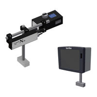
Kortho GraphicJet X Series Inkjet Printer Manuals
Manuals and User Guides for Kortho GraphicJet X Series Inkjet Printer. We have
2
Kortho GraphicJet X Series Inkjet Printer manuals available for free PDF download: Manual
Kortho GraphicJet X Series Manual (236 pages)
Brand:
Kortho
| Category:
Printer
| Size: 19 MB
Table of Contents
Table of Contents
5
Preface
3
Symbols in this Manual
3
Table of Contents
5
1 Introduction
9
Qualified Personnel
9
Elementary Personal Protection
9
Intended Use
9
Specifications
10
Coding Unit
10
Control Unit
11
Ink
12
Label Features
12
Life Span
13
Electrostatic Charge
13
Shock & Vibration
13
2 Technical Description
15
The Print System
15
Coding Unit
16
Control Unit
17
Sensors
19
Photocell
19
Encoder
19
Label Design
20
Integrated Label Design Program
20
Nicelabel
20
3 Print Process Description
21
Print Cycle
21
Printhead
21
Ink System
22
Spit Function
22
User Interface
23
Menu Structure
23
LED Indicators on Control Unit
23
Keyboard
24
System Information
28
Menu Structure
29
4 Safety
31
General
31
Control Unit
31
General Information
31
Power Supply
32
Precautions before Power-Up
32
Precautions When Opening the Control Unit
33
Anti-Static Precautions
33
Printhead
33
Printed Circuit Boards
33
Ink and Cleaner
34
General Safety Measures
34
First Aid Measures
34
Warning Labels
34
Caution Labels
34
5 Transport & Storage
35
Printer Equipment
35
Shipping and Handling
35
Pre-Transport Procedure
35
Pre-Storage Procedure
36
Ink and Cleaner
38
Handling and Storage
38
Transport Information
38
6 Installation
39
Requirements
39
Provided by the Customer
39
Equipment
39
Optional Parts
39
Unpacking
40
Coding Unit
40
Control Unit
41
Encoder (Optional)
41
Ink Set
42
Coding Unit Mounting Options
42
Distance between Front Plate and Product
42
Ink Reservoir
43
Ink Reservoir Orientation
43
Printhead Rotation [X54] [X72]
44
Radial Printhead Rotation
44
Axial Printhead Rotation [X54] [X72]
47
Radial and Axial Printhead Rotation [X54] [X72]
49
Positioning the Sensors
50
Photocell for Print Request (X04)
50
Photocell to Enter BCD Code into the Buffer (X08)
50
Encoder (Optional)
51
Mounting the Control Unit
52
7 Commissioning
53
Preparing the Control Unit
53
Filling the Ink System
54
Tuning the Speed Related Parameters
57
Preparing for the First Test Print
57
Tuning the Test Print with the Encoder Disabled
59
Tuning the Test Print with the Encoder Enabled
60
General Print Parameter Settings
60
Changing the Print Direction
60
Changing the Print Direction and Mirroring the Label
61
Setting the Print Request Parameters
61
Spit Parameter Settings
62
Setting the Spit Parameters
62
Setting the Ink Low and Ink out Outputs
64
User Settings
64
8 Operation
67
Powering up
67
Operational
68
Start Printing
68
Operator Data Input
68
Text Item Input Menu
69
Date Advance Input Menu
70
Number Start Value Input Menu
70
Label Management
71
Selecting a Label for Printing
71
List Labels (Local Files)
72
Add Labels
72
Moving a Label
74
Deleting a Label
75
Editing a Label
76
Creating a Label
77
Showing a Preview
81
Re-Filling the Ink Reservoir
82
Purging the Printhead
83
Priming the Printhead
84
Adjusting Printer Settings
85
System Settings
86
Printer Settings
91
Signal Settings
94
Network Settings
98
Label Settings
101
Print Settings
103
Specific Settings for the Tsc20-Duo
105
9 Diagnostics / Troubleshooting
107
Service
107
Test Labels
107
Fonts
108
Test
112
Printer
114
Diagnostics
116
Graphics
118
Information
121
General
121
Health
122
Backup
122
System Info
124
Report
125
Upgrade
127
Fault Finding
129
Control Unit
129
Coding Unit
130
Print Request Sensor
132
Encoder
132
Error/Warning Messages
133
Poor Print Quality
133
General Issues
133
Often Seen Print Results
135
10 Maintenance
137
Quick and Regular Checks
137
Nozzle Maintenance
137
Yearly Maintenance
137
Replacing Parts of the Printhead Housing
137
Anti-Static Precautions
137
Open the Printhead Housing
138
Close the Printhead Housing
139
Replacing the Printhead PCB [X18, X18Si, X18+]
139
Replacing the Printhead PCB [X54]
140
Replacing the Printhead PCB [X72]
141
Replacing the Piezo Printhead [X18, X18Si, X18+]
142
Replacing the Piezo Printhead [X54]
142
Replacing the Piezo Printhead [X72]
143
Replacing the Ink Filter
144
Updating Firmware and Software
144
11 Dismantling & Disposal
145
Dismantling
145
System
145
Ink Reservoir
145
Printhead Housing
145
Control Unit
145
Sensor Devices
145
Ink and Cleaner
146
Disposal
146
Disposal Method
146
Waste Separation
146
Index
147
Appendix B Dimensions
157
Appendix B Dimensions
158
Coding Unit X18, X18*+ and X18Si and Bracket
158
Coding Unit X54 and Bracket
159
Coding Unit X72 and Bracket
160
Control Unit
161
Control Unit and Bracket
162
Appendix A Specifications
163
Appendix C Part Lists & Illustrations
163
Appendix D Connections
175
Appendix D Connections
176
Control Unit Connector Plate
176
X3 Schematic Diagram (Input
177
X3 Schematic Diagram (Output
178
X3 Circuit Diagram (Input
179
X3 Circuit Diagram (Output
180
X3 Schematics Diagram User
181
Appendix E Nicelabel Driver Tutorials
185
Appendix E Nicelabel Driver Tutorials
186
Installation and Configuration of the Driver
186
Function of the Driver
186
Versions of the Driver
186
Installation of the Driver
187
Configuration of the Driver
190
Summary
192
Downloading a Label through USB
193
Introduction
193
Installation of the Driver
193
Download a Label through USB
194
Sending a Label on a Network
195
Introduction
195
Installation of the Driver
195
Appendix F Quick Reference Menu Structure
197
Appendix G Error List
199
Appendix H Using the BCD Label Selection
203
Appendix I Using Variables in Labels
209
Appendix J Setting and Using the Security Option
221
Appendix K Restore Factory Settings Using Dipswitch
225
Appendix L the Automation Feature
227
Appendix M Selecting and Updating a Label over TCP/IP
229
Appendix N Remapping Inputs & Outputs
233
Appendix Oec Declaration of Conformity
235
Advertisement
Kortho GraphicJet X Series Manual (178 pages)
Brand:
Kortho
| Category:
Printer
| Size: 10 MB
Table of Contents
Table of Contents
5
Symbols in this Manual
3
Preface
3
Glossary
4
Table of Contents
5
Introduction
11
Qualified Personnel
11
Elementary Personal Protection
11
Intended Use
11
Specifications
12
Coding Unit
12
Fig. 1.1 Coding Units, Global Dimensions
12
Control Unit
13
Ink
13
Fig. 1.2 Control Unit, Global Dimensions
13
Label Features
14
Shock & Vibration
15
Life Span
15
Electrostatic Charge
15
Technical Description
17
The Print System
17
Fig. 2.1 the Printer System
17
Coding Unit
18
Fig. 2.2 Coding Unit, Parts
18
Fig. 2.3 Ink Reservoir, Parts
18
Fig. 2.4 Printhead Housing, Parts
19
Fig. 2.5 Printhead Interior, Parts
19
Control Unit
20
Fig. 2.7 Control Unit, Connections
20
Fig. 2.9 Encoder
21
Fig. 2.8 Photocell
21
Encoder
21
Photocell
21
Sensors
21
Label Design
22
Integrated Label Design Program
22
Nicelabel
22
Print Process Description
23
Print Cycle
23
Printhead
23
Fig. 3.1 Piezo Printhead Technology
23
Ink System
24
User Interface
24
Fig. 3.2 Printhead and Ink Levels
24
Fig. 3.3 Screen Layout
25
Keyboard
25
LED Indicators on Control Unit
25
Menu Structure
25
Fig. 3.4 First Keyboard Screen
26
Fig. 3.5 Arabic Keyboard
26
Fig. 3.6 First Keyboard Screen, Alternative Alphanumerics
27
Fig. 3.7 Second Keyboard Screen, Numerics and Special Characters
27
Fig. 3.8 Third Keyboard Screen, Commonly Used Text
28
Fig. 3.9 Programming Third Keyboard Screen Buttons, Entering Text
28
Fig. 3.10 Programming Third Keyboard Screen Buttons, Entering Text
29
Fig. 3.11 Fourth Keyboard Screen, Edit Text and Use Cursor Controls
29
System Information
30
Fig. 3.12 Numeric Keyboard
30
Fig. 3.13 Entering the System Information Screen
30
Menu Structure
31
Fig. 4.2 Power Supply Information
33
Fig. 4.1 Control Unit Identification Label
33
Power Supply
33
General Information
33
Safety
33
Control Unit
33
Precautions before Power-Up
34
Precautions When Opening the Control Unit
34
Fig. 4.3 Attention Label for Opening Control Unit
34
Ink and Solvent
35
General Safety Measures
35
Printed Circuit Boards
35
Anti-Static Precautions
35
Printhead
35
First Aid Measures
36
Warning Labels
36
Caution Labels
36
Fig. 4.4 Ink Reservoir Labels, Screw Cap and Refill
36
Pre-Transport Procedure
37
Fig. 5.1 Shipping and Handling Labels
37
Transport & Storage
37
Shipping and Handling
37
Printer Equipment
37
Pre-Storage Procedure
38
Ink and Solvent
39
Handling and Storage
39
Transport Information
40
Installation
41
Requirements
41
Provided by the Customer
41
Equipment
41
Optional Parts
41
Fig. 6.2 Coding Unit X18
42
Fig. 6.1 Typical Printer Application
42
Codingunit
42
Unpacking
42
Control Unit
43
Encoder (Optional)
43
Fig. 2.6 Control Unit
43
Fig. 6.3 Control Unit Tsc20
43
Fig. 6.4 Encoder with Support
43
Ink Set
44
Coding Unit Mounting Options
44
Distance between Front Plate and Product
44
Ink Reservoir
44
Fig. 6.5 Distance between Front Plate and Product
44
Fig. 6.6 Ink Reservoir Mounting Clamp Heights
44
Fig. 6.8 Perpendicular Reservoir
45
Fig. 6.7 Parallel Reservoir
45
Printhead Rotation
45
Ink Reservoir Orientation
45
Radial Printhead Rotation
46
Fig. 6.9 Printhead Clamp Mounting Options Yyy
46
Fig. 6.10 Printhead Radial Rotation 0°, Standard Support, Clamp Down, Reservoir Position I
46
Fig. 6.13 Printhead Radial Rotation Graph
48
Axial Printhead Rotation
49
Fig. 6.14 Printhead Axial Rotation 0°, 45° and 90°, Clamp Down, Reservoir Position I
49
Fig. 6.15 Printhead Axial Rotation -45°, Clamp Up, Reservoir Position
49
Fig. 6.16 Printhead Axial Rotation Graph
50
Radial and Axial Printhead Rotation
51
Positioning the Sensors
52
Photocell
52
Print Safety Photocell (Optional)
52
Fig. 6.17 Photocell Positions
52
Fig. 6.18 Photocell Distance to the Product
52
Fig. 6.19 Encoder Adjustment
53
Mounting the Control Unit
53
Encoder (Optional)
53
Commissioning
55
Preparing the Control Unit
55
Fig. 7.1 Main Menu
55
Fig. 7.2 Printer Settings Menu
55
Filling the Ink System
56
Fig. 7.3 Printhead Housing at Horizontal Position
56
Fig. 7.4 Cut Ink Bottle Open
56
Fig. 7.5 Ink Reservoir Opened
57
Fig. 7.6 Ink Reservoir with Ink Bottle Placed
57
Tuning the Speed Related Parameters
58
Preparing for the First Test Print
58
Fig. 7.7 Ink Reservoir with Prime Bulb
58
Fig. 7.9 Diagnostics - Testlabel Menu
59
Fig. 7.8 Settings Menu
59
Tuning the Test Print with the Encoder Disabled
60
Fig. 7.10 Diagnostics - Test Menu
60
Tuning the Test Print with the Encoder Enabled
61
General Print Parameter Settings
61
Changing the Print Direction
61
Fig. 7.11 Test Label Printed at Correct Speed Setting
61
Changing the Print Rotation Angle
62
Setting the Print Request Parameters
62
Spit Parameter Settings
63
Setting the Spit Parameters
63
Setting the Ink Low and Ink out Outputs
64
User Settings
65
Operation
67
Powering up
67
Operator Data Input
68
Start Printing
68
Operational
68
Text Item Input Menu
69
Date Advance Input Menu
70
Number Start Value Input Menu
70
Label Management
71
Selecting a Label for Printing
71
Moving a Label
73
Deleting a Label
74
Editing a Label
75
Creating a Label
76
Showing a Preview
79
Filling the Ink Reservoir
80
Purging the Printhead
81
Priming the Printhead
82
Adjusting Printer Settings
83
System Settings
84
Printer Settings
87
Signal Settings
88
Network Settings
89
Label Settings
90
Print Settings
92
Diagnostics / Troubleshooting
95
Diagnostics
95
Test Labels
95
Fonts
96
Test
99
Printer
100
Diagnostics
103
Graphics
104
Information
107
General
107
Health
108
Backup
108
Report
110
System Info
110
Upgrade
112
Fault Finding
113
Control Unit
113
Coding Unit
115
Print Request Signal Sensor
116
Encoder
116
Error/Warning Messages
117
Poor Print Quality
117
General Issues
117
Common Print Results
118
Nozzle Maintenance
121
Maintenance
121
Quick and Regular Checks
121
Yearly Maintenance
122
Replacing Parts of the Printhead Housing
122
Anti-Static Precautions
122
Open the Printhead Housing
122
Close the Printhead Housing
123
Replacing the Printhead PCB
123
Replacing the Piezo Printhead
124
Replacing the Ink Filter
125
Updating System Software
125
Printhead Housing
127
Control Unit
127
Sensor Devices
127
Ink Reservoir
127
System
127
Dismantling
127
Dismantling & Disposal
127
Ink and Solvent
128
Disposal
128
Disposal Method
128
Waste Separation
128
Index
129
Figures
132
Appendix A Specifications
135
Appendix B Dimensions
139
Appendix C Part Lists & Illustrations
143
Appendix D Connections
151
Appendix D Connections
152
Control Unit Connector Plate
152
X3 Schematic Diagram (Input
153
X3 Schematic Diagram (Output
154
X3 Circuit Diagram (Input
155
X3 Circuit Diagram (Output
156
X3 Schematics Diagram User
157
Appendix E Nicelabel Driver Tutorials
159
Appendix E Nicelabel Driver Tutorials
160
Function of the Driver
160
Installation and Configuration of the Driver
160
Versions of the Driver
160
Installation of the Driver
161
Configuration of the Driver
164
Downloading a Label through USB
167
Installation of the Driver
167
Introduction
167
Download a Label through USB
168
Installation of the Driver
169
Introduction
169
Sending a Label on a Network
169
Appendix F Quick Reference
173
Appendix G Error List
175
Advertisement
Related Products
Kortho 814532
Kortho 814561
Kortho 819528
Kortho GraphicJet KGJ X18
Kortho GraphicJet KGJ X18si
Kortho GraphicJet KGJ X54
Kortho GraphicJet KGJ X72
Kortho GraphicJet TsC20-X duo
Kortho GraphicJet X18 Series
Kortho Categories
Printer
Label Maker
Media Converter
More Kortho Manuals
Login
Sign In
OR
Sign in with Facebook
Sign in with Google
Upload manual
Upload from disk
Upload from URL