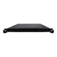
Sign In
Upload
Manuals
Brands
Kontron Manuals
Server
RAK-100S-DNV
Kontron RAK-100S-DNV Manuals
Manuals and User Guides for Kontron RAK-100S-DNV. We have
1
Kontron RAK-100S-DNV manual available for free PDF download: User Manual
Kontron RAK-100S-DNV User Manual (77 pages)
Brand:
Kontron
| Category:
Server
| Size: 1.77 MB
Table of Contents
Symbols
6
For Your Safety
7
High Voltage Safety Instructions
7
Special Handling and Unpacking Instruction
7
Lithium Battery Precautions
8
General Instructions on Usage
8
Quality and Environmental Management
8
Disposal and Recycling
8
WEEE Compliance
8
Table of Contents
9
List of Tables
11
List of Figures
11
1/ General Safety Instructions for IT Equipment
13
Electrostatic Discharge (ESD)
15
Grounding Methods
15
Lithium Battery Replacement
15
2/ Electromagnetic Compatibility
17
Electromagnetic Compatibility (EU)
17
FCC Statement (USA)
17
EMC Compliance (Canada)
17
3/ Shipment and Unpacking
18
Unpacking
18
Scope of Delivery
18
Standard
18
Optional Parts
18
4/ System Overview
19
System Expansion Capabilities
20
System Expansion Via SATA Interface
20
System Expansion Via M.2 Interface
20
System Expansion Via Msata / Mpcie Interface
20
System Expansion Via Pcie X16 Add-On Card Slot
20
Front I/O Panel
21
Power Switch
21
Power LED
21
Storage LED
21
Usb 2.0
21
Figure 1: Front I/O Panel
21
Rear I/O Panel
22
AC-In Power Socket
22
Vga
22
Gbe LAN
22
Figure 2: Rear I/O Panel
22
Figure 3: Ethernet LED Status
22
Usb 3.0
23
Rs232/422/485
23
Accessible Bay for Pcie X16 Add-On Card Slot
23
Antenna Port
23
Internal View
24
DDR4 UDIMM Memory Socket
24
Figure 4: Internal View (Without Cover)
24
SATA Power Connector & SATA Power Cable
25
Socket
25
Msata / Mpcie Socket
25
Pcie X16 Add-On Card Slot
25
Table 1: Pin Assignment JP1
25
Figure 5: Msata / Mpcie Selection Jumper JP1
25
5/ Accessing Internal Components
26
Opening and Closing the Chassis
27
Figure 6: Descrewing the Access Cover of the RAK-100S-DNV
27
Figure 7: Disengaging the Access Cover
27
Installing UDIMM Memory Module(S)
28
Installing HDD(S) / SSD(S)
28
Installing an M.2 SSD
29
Installing an Msata SSD / Mpcie Expansion Card
29
6/ Thermal Considerations
30
Available Processors
30
Convection Cooling
30
System Clearance
30
Maximum Temperatures
30
Third Party Components
30
7/ Installation Instructions
32
System Mounting
33
Figure 8: Optional Rackmount Server Slide Kit
33
Figure 9: Removing the Chassis (Inner) Slide Rail
33
Figure 10: Mounting the Chassis (Inner) Slide Rail to the Server Chassis
34
Figure 11: Attaching the Cabinet (Outer) Slide Rail to the Rack Rail
34
Figure 12: Inserting the Chassis (Inner) Slide Rail into the Cabinet (Outer) Rail
35
Figure 13: Mounting the Server into the Rack Cabinet
35
Figure 14: Securing the Server
36
AC Power Connection
37
8/ Start up
38
Connecting to DC Power Supply
38
Operating System and Hardware Component Drivers
39
9/ Maintenance and Cleaning
40
Technical Specifications
41
Table 2: Technical Specifications
41
Mechanical Specifications
42
Mechanical Drawing
42
Table 3: Mechanical Specifications
42
Figure 15: Mechanical Drawing
42
Environmental Conditions
43
Standards and Certifications
43
Table 4: Environmental Conditions
43
Table 5: Standards and Certifications
43
11/ Standard Interfaces - Pin Assignments
44
AC-In Power Socket
44
Ethernet Connector
44
USB 3.0 Port
44
USB 2.0 Port
44
Table 6: AC-In Power Socket (See Figure 2, Pos. 1)
44
Table 7: Ethernet Connector (See Figure 2, Pos. 3)
44
Table 8: USB 3.0 Port (See Figure 2, Pos. 4)
44
Table 9: USB 2.0 Port (See Figure 1, Pos. 4)
44
VGA Connector
45
RS232/422/485 Serial Port
45
Table 10: VGA Connector (See Figure 2, Pos. 2)
45
Table 11: RS232/422/485 Serial Port (See Figure 2, Pos. 5)
45
12/ Bios
46
Starting the Uefi BIOS
46
Table 12: Hotkeys Table
46
Starting the Uefi BIOS
47
Main Setup Menu
47
Table 13: Main Setup Menu Sub-Screens and Functions
47
Figure 16: BIOS Main Menu Screen System Data and Time
48
Advanced Setup Menu
49
Figure 17: BIOS Advanced Menu
50
Figure 18: BIOS Advanced Menu - FIA HSIO12 Configuration
51
Figure 19: BIOS Advanced Menu - CPU Chipset Configuration
53
Figure 20: BIOS Advanced Menu - Nvme Configuration
54
Figure 21: BIOS Advanced Menu - SATA Configuration
55
Figure 22: BIOS Advanced Menu - USB Configuration
56
Figure 23: BIOS Advanced Menu - Trusted Computing
57
Figure 24: BIOS Advanced Menu - Network Stack Configuration
58
Figure 25: BIOS Advanced Menu - Super IO Configuration
59
Figure 26: BIOS Advanced Menu - Super IO Configuration - Serial Port 1 Configuration
59
Figure 27: BIOS Advanced Menu - Super IO Configuration - Serial Port 2 Configuration
60
Figure 28: BIOS Advanced Menu - Serial Port Console Redirection
61
Figure 29: BIOS Advanced Menu - Serial Port Console Redirection - COM1 Console Redirection Settings
62
Figure 30: BIOS Advanced Menu - Serial Port Console Redirection - COM2 Console Redirection Settings
64
Figure 31: BIOS Advanced Menu - Serial Port Console Redirection - Legacy Console Redirection Settings
66
Figure 32: BIOS Advanced Menu - Serial Port Console Redirection - Out-Of-Band Mgmt Port Console Redirection Settings
67
Figure 33: BIOS Advanced Menu - H/W Monitor
68
Power Setup Menu
69
Figure 34: BIOS Power Setup Menu
69
Figure 35: BIOS Power Setup Menu - Watchdog Timer Configuration
70
Boot Setup Menu
71
Figure 36: BIOS Boot Setup Menu
71
Security Setup Menu
73
Save & Exit Setup Menu
75
Appendix A: List of Acronyms
76
Table 14: List of Acronyms
76
About Kontron
77
Advertisement
Advertisement
Related Products
Kontron Revolution plus
Kontron RMX-BKB104
Kontron R4U8S
Kontron RTM806X
Kontron AdvancedTCA RTM8020
Kontron RMVS-KVMS08A
Kontron RMVS-1U
Kontron RMX-1U15TFTB
Kontron CC2800
Kontron CG1200
Kontron Categories
Computer Hardware
Motherboard
Server
Desktop
PCI Card
More Kontron Manuals
Login
Sign In
OR
Sign in with Facebook
Sign in with Google
Upload manual
Upload from disk
Upload from URL