Sign In
Upload
Manuals
Brands
Kontron Manuals
Switch
RES2404-PTP-PoE
Kontron RES2404-PTP-PoE Manuals
Manuals and User Guides for Kontron RES2404-PTP-PoE. We have
1
Kontron RES2404-PTP-PoE manual available for free PDF download: User Manual
Kontron RES2404-PTP-PoE User Manual (34 pages)
Brand:
Kontron
| Category:
Switch
| Size: 3 MB
Table of Contents
Table of Contents
8
1 / Introduction
10
Table 1: Product Variants
10
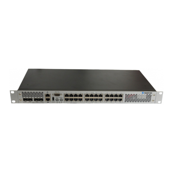
RES2404-PTP-Poe Operational View
11
Figure 1: RES2404-PTP-Poe Operational Front View
11
Figure 2: RES2404-PTP-Poe Operational Back View
11
Figure 3: RES2404-PTP-Poe Inside View
11
Hardware Components
12
Software Components
12
Table 2: Software Specification
12
Technical Data
14
Table 3: Technical Data
14
Table 4: Environmental Conditions
15
2 / Getting Started with RES2404-PTP-Poe
16
Receipt of the Equipment
16
Checking the Packages
16
Unpacking
16
External Connectors
17
Ethernet Connectors (I/O Area)
17
Table 5: Pin Assignment Connector
17
Table 6: Signal Description
17
Figure 4: Ethernet Connector, Status Leds See Table 11: Status Leds
17
Small Form-Factor Pluggable (SFP+) Connector for 10Gbe
18
Table 7: SFP+ Connector
18
Figure 5: Small Form-Factor Pluggable (SFP+) Standard Connector for Gbe/10Gbe
18
Ethernet Port Mapping
19
Table 8: Ethernet Port Mapping
19
Dual RJ45 Connector
20
Table 9: Management-Port
20
Table 10: RS232
20
Figure 6: Dual RJ45 Connector (Red Circle)
20
3 / Device Management
21
Power and Status Leds
21
Table 11: Status Leds
21
Figure 7: Status Leds on RES2404-PTP-Poe (Red Circle)
21
Link Activity Poe Speed Leds for Gbe Ports
22
Power over Ethernet (Poe) Distribution
22
Table 12: Leds Link, Activity and Poe
22
Figure 8: Gbe-Ports with Leds
22
Figure 9: 10Gbe-Ports with Leds
22
Programming the Carrier ID (CID) with DIP Switches
23
Table 13: DIP Switch 1
23
Table 14: DIP Switch 2
23
Figure 10: Rotary DIP Switches
23
Restart by Pressing Reset Button
24
Table 15: POST Routines after Reset
24
Figure 11: Reset Button (in the Red Circle)
24
Alarm out
25
Table 16: Alarm out Connector
25
Figure 12: Alarm out Connector (in the Red Circle)
25
4 / Installation
26
Safety Requirements
26
Cooling
26
Mounting Variants
27
Precision Time Protocol (PTP)
27
Figure 13: Mounting Variants
27
Switch Configuration Access
29
Serial Port Access
29
Out-Of-Band Access Via Network
29
Figure 14: Admin Interfaces: Serial Service Port (Lower) and Ethernet Service Port (Upper)
29
In-Band Access Via Network
30
Firmware Administration
31
Firmware Description
31
Failsave Update
31
Update Procedure
31
Advertisement
Advertisement
Related Products
Kontron RMVS KVM Series
Kontron RMVS-KVMS08A
Kontron RMVS-KVMS16A
Kontron RMVS-1U.XXXB
Kontron RMVS-1U.XXXC
Kontron KSwitch R20
Kontron Revolution plus
Kontron RMX-BKB104/DRWR
Kontron RMX-9U15L
Kontron KBox R-101-TGL
Kontron Categories
Computer Hardware
Motherboard
Server
Industrial PC
Desktop
More Kontron Manuals
Login
Sign In
OR
Sign in with Facebook
Sign in with Google
Upload manual
Upload from disk
Upload from URL