Sign In
Upload
Manuals
Brands
Kontron Manuals
Industrial PC
KISS 2U V3
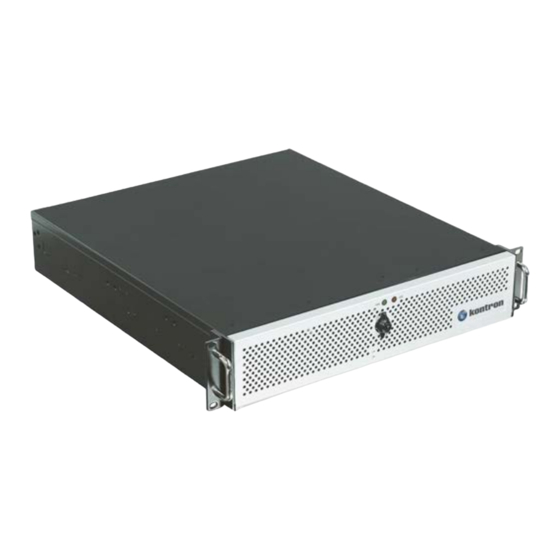
Kontron KISS 2U V3 Rack Mount Server Manuals
Manuals and User Guides for Kontron KISS 2U V3 Rack Mount Server. We have
1
Kontron KISS 2U V3 Rack Mount Server manual available for free PDF download: User Manual
Kontron KISS 2U V3 User Manual (67 pages)
Brand:
Kontron
| Category:
Industrial PC
| Size: 5.74 MB
Table of Contents
Symbols
6
For Your Safety
7
High Voltage Safety Instructions
7
Special Handling and Unpacking Instruction
7
Lithium Battery Precautions
8
General Instructions on Usage
8
Quality and Environmental Management
8
Disposal and Recycling
8
WEEE Compliance
8
Table of Contents
9
List of Tables
11
List of Figures
11
1 / General Safety Instructions for IT Equipment
13
Operation of Laser Source Devices
14
Figure 1: Laser Radiation Warning Label
14
Electrostatic Discharge (ESD)
15
Grounding Methods
15
Instructions for the Lithium Battery
15
2 / Introduction
16
3 / Scope of Delivery
17
Accessories and Spare Parts
17
Shipment, Packaging and Unpacking
17
Type Label
17
Table 1: Scope of Delivery
17
Table 2: Accessories and Spares Parts
17
Figure 2: Type Label Example
17
4 / Product Description
18
Figure 3: Rackmount Variant (Closed Front Access Panel)
18
Figure 4: Desktop Variant (Closed Front Access Panel)
18
Figure 5: Rackmount Variant (Opened Front Access Panel)
18
Figure 6: Desktop Variant (Opened Front Access Panel)
18
Front Side
19
Figure 7: Front Side with Front Access Panel Closed
19
Figure 8: Handle Bracket with Fastening Screws
19
Figure 9: Front Side with Front Access Panel Open
20
USB Ports
21
Controls and Indicators
21
Figure 10: Power Button and USB 2.0 Ports
21
Front Access Panel
22
Table 3: Power LED and HDD LED Activity
22
Figure 11: LED Indicators
22
Fan Assembly
23
Filter Pad and Filter Pad Holder
23
Figure 12: Fan Assembly
23
Drive Bays
24
Table 4: Drive Bays
24
Rear Side
25
Figure 13: Rear Side with Micro-ATX Mainboard with Riser Card
25
Figure 14: Rear Side with Micro-ATX Mainboard with Low Profile Cards
26
Figure 15: Rear Side with SBC
26
Interfaces on the Rear Side
27
Figure 16: External Mainboard Interface Panel KISS 2U V3 CFL
27
Figure 17: External Mainboard Interface Panel KISS 2U V3 PCI763
27
Additional Serial Ports
28
Power Supply Unit
28
Potential Equalization Stud
28
Figure 18: PSU 400W AC
28
Sides (Left and Right)
29
Figure 19: Left Side
29
Figure 20: Right Side
29
Cover
30
Figure 21: Cover Underside
30
System Configuration
31
System Configuration with Mainboard and Low Profile Expansion Cards
31
Figure 22: Example of KISS 2U V3 Configuration with Mainboard and Low Profile Expansion Cards
31
System Configuration with Mainboard and Riser Card Expansion Cards
32
Figure 23: Example of KISS 2U V3 Configuration with Mainboard and Riser Expansion Cards
32
System Configuration with SBC
33
Figure 24: Example of KISS 2U V3 Configuration with SBC
33
5 / System Extension
34
Mass Storage Options
34
Expansion Cards
34
Table 5: Mass Storage Devices
34
Table 6: Expansion Slots
34
Figure 25: Pcie/Pci Expansion Slots Type and Location - PICMG 1.3 Backplane SBC Variant
35
6 / Thermal Considerations
36
Active Cooling
36
Minimum System Clearance
36
Third Party Components
36
7 / Assembly
37
Opening and Closing the Cover
37
Figure 26: Loosening Knurled Screw on the Front Side
37
Figure 27: Loosening Knurled Screws on the Rear Side
37
Figure 28: Pull and Release the Cover
37
Figure 29: Removing the Cover
38
Accessing Internal Components
39
Installing and Removing Riser Card and SBC Expansion Cards
39
Figure 30: Pulled-Out Card Cage for SBC and Mainboard with Riser Card
39
Installing and Removing Low Profile Expansion Cards
40
8 / Installation
41
Installing the Rubber Feet
41
Removing the Handle Brackets
42
Removing the Front Access Panel and Front Access Panel Side-Plates
42
Figure 31: Front Access Panel Side-Plate and Handle Bracket
42
Installing as a Desktop
43
Installing in a 19" Industrial Rack
43
Installing Slide Rails (Option)
44
Figure 32: Slide Rail Inner Part Fastened to Chassis
45
Figure 33: Slide Rail in Pulled-Out Position
45
Figure 34: Slide Rail in Pushed-In Position
45
Figure 35: Assembling the Slide Rails in an Industrial Rack Cabinet
46
9 / Starting up
47
Connecting the Power Connection
47
Figure 36: Input Power Socket
47
Operating System and Hardware Component Drivers
48
10 / Maintenance and Prevention
49
Cleaning the Filter Pad
49
Figure 37: Front Side with Filter Pad Holder
49
Figure 38: Front Side Without Filter Pad
50
Figure 39: Filter Pad Holder (Without Filter Pad)
50
Figure 40: Filter Pad Holder (with Filter Pad)
50
Figure 41: Filter Pad
50
Replacing the Fan Assembly
51
Figure 42: Removing the Fan Assembly
51
Replacing the Lithium Battery
52
11 / Technical Data
53
Block Diagrams
53
Block Diagram KISS 2U V3 CFL
53
Block KISS 2U V3 PCI763
54
Technical Specification
55
Mechanical Specification
56
Environmental Specification
56
Directives and Standards
57
12 / Standard Interfaces- Pin Assignments
58
Keyboard Connector Pin Assignment
58
PS/2 Mouse Connector Pin Assignment
58
USB 2.0 Pin Assignment
58
Display Port Pin Assignment
59
COM 1 Pin Assignment
59
DVI_D Connector Pin Assignment
59
DVI-I Connector Pin Assignment
60
LAN Connector Pin Assignment
60
USB 3.0 and USB 3.1 (Gen1/Gen2) Type a Pin Assignment
60
Audio Jack Pin Assignment
61
13 / Technical Support
62
Returning Defective Merchandise
62
14 / Storage and Transportation
64
Storage
64
Transportation
64
15 / Warranty
65
Limitation/Exemption from Warranty Obligation
65
Appendix A: List of Acronyms
66
Table 7: List of Acronyms
66
About Kontron
67
Advertisement
Advertisement
Related Products
Kontron KISS 2U V2
Kontron KISS 2U V3 PCI763
Kontron KISS 2U V2 KTQ87-A
Kontron KISS 2U V2 PCI762-A
Kontron Kiss 2U
Kontron 2-A0HC Series
Kontron 22201
Kontron 2-DH47-0010
Kontron MediClient 23.8"
Kontron MediClient 21.5"
Kontron Categories
Computer Hardware
Motherboard
Server
Desktop
PCI Card
More Kontron Manuals
Login
Sign In
OR
Sign in with Facebook
Sign in with Google
Upload manual
Upload from disk
Upload from URL