Sign In
Upload
Manuals
Brands
Kontron Manuals
Industrial PC
KBox A-103
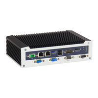
Kontron KBox A-103 Industrial Box PC Manuals
Manuals and User Guides for Kontron KBox A-103 Industrial Box PC. We have
1
Kontron KBox A-103 Industrial Box PC manual available for free PDF download: User Manual
Kontron KBox A-103 User Manual (88 pages)
Brand:
Kontron
| Category:
Industrial PC
| Size: 9 MB
Table of Contents
Symbols
6
For Your Safety
7
High Voltage Safety Instructions
7
Special Handling and Unpacking Instruction
7
Lithium Battery Precautions
8
General Instructions on Usage
8
Quality and Environmental Management
8
Disposal and Recycling
8
WEEE Compliance
8
Table of Contents
9
List of Tables
11
List of Figures
12
1 / General Safety Instructions for IT Equipment
14
Electrostatic Discharge (ESD)
16
Grounding Methods
16
Instructions for the Optional Lithium Battery
16
2 / Electromagnetic Compatibility
17
Electromagnetic Compatibility (EU)
17
FCC Statement (USA)
17
EMC Compliance (Canada)
17
3 / Shipment and Unpacking
18
Unpacking
18
Scope of Delivery
18
Standard
18
Optional Parts
18
Optional System Extension
18
Type Label and Product Identification
19
Figure 1: Type Label
19
4 / System Overview
20
Rtc
21
RTC Buffer Time
21
Figure 2: RTC Buffer Time Diagram
21
Setting the RTC
22
System Expansion Capabilities
23
System Expansion Via SATA Interface
23
System Expansion Via Msata Interface
23
System Expansion Via Mini PCI Express® (Mpcie) Card Interfaces (with SIM Card Socket)
23
Figure 3: Bottom Side View
24
Figure 4: Right Side View
24
Figure 5: Front Side View Config. with Vertical Mounting Plate
24
Figure 6: Left Side View
24
Figure 7: Top Side View
24
Figure 8: Rear Side View
24
Block Diagram of the Kbox A-103
25
Figure 9: Block Diagram of the Kbox A-103
25
Front Side
26
Figure 10: Kbox A-103 - Front View
26
X101 - Power Input Connector
27
Controls and LED Indicators
27
Figure 11: X101 - 24VDC Power Input Connector
27
Figure 12: Detail - Power Button and PWR LED and HDD LED
27
X102/X103 - Ethernet Connectors (ETH)
28
X105 - Usb 3.0
28
X107/X108 - Usb 2.0
28
X109 - Displayport
28
X110 - Serial Port COM 1
28
X204 - Serial Port COM 2 (Option)
28
X206 - Serial Port COM 3 (Option)
28
X205 - FIELDBUS Interface (Option)
29
X207 - VGA Interface Connector
29
Figure 13: X205 - Optional FIELDBUS Interface
29
Left and Right Side View
30
Top and Bottom Side View
30
Figure 14: Right Side of the Kbox A-103 System
30
Figure 15: Left Side of the Kbox A-103 System
30
Figure 16: Top Side of the Kbox A-103 System
30
Figure 17: Bottom Side of the Kbox A-103 System
30
Rear Side View
31
Rear Side View of the Kbox A-103 with Vertical Mounting Bracket
31
Figure 18: Rear Side of the Kbox A-103 System with Vertical Mounting Plate
31
Rear Side View of the Kbox A-103 as Desktop Unit or with Wallmount Bracket
32
Figure 19: Rear Side of the Kbox A-103 Without Optional WLAN and GPIO (Shown as Desktop Unit)
32
Figure 20: Rear Side of the Kbox A-103 with Optional WLAN and GPIO (Shown with Vertical/Horizontal Mounting Brackets)
32
DIN Rail Clip (Option)
33
Wifi/Wlan (Option)
33
GPIO Interface (Option)
33
Figure 21: DIN Rail Clip
33
Figure 22: WLAN (Wifi) Antenna
33
Internal View
34
Figure 23: Kbox A-103 - Internal View (Without Cover)
34
Integrated SMARC-Sxbti Module
35
SATA Interface
35
Msata Socket
35
Expansion Slots for Mpcie Cards
35
5 / Accessing Internal Components
36
Opening and Closing the Kbox A-103
37
Figure 24: Opening the Access Cover of the Kbox A-103
37
Access Cover
38
Figure 25: Inside of the Access Cover
38
Serial Port COM2 (X204) Configuration for RS422 or RS485 Via DIP Switches
39
Figure 26: DIP1-DIP8 Switches (Shown with Factory Settings)
39
Figure 27: DIP-Switch (SW1) with DP1 to DP8 for RS422/RS485 Serial Communication Settings (for COM 2)
39
Table 1: DIP1, DIP2 and DIP3 Settings for Serial Communication Type
40
Table 2: DIP4 Setting in Order to Activate or Deactivate the Termination Resistor
40
Table 3: DIP5, DIP6, DIP7 and DIP8 Settings in Order to Set the Needed Timeout and Min. Baud Rate
40
Serial Port COM 3 (X206) Configuration of the Serial Port COM 3
41
Table 4: J46 Settings Forcom 3 RS485 and RS422 Modes (Factory Settings Are in Bold Letters)
41
Optional GPIO Port
42
Installing an Mpcie Mini Card
42
Table 5: Pin Assignments of Internal and External GPIO Connector
42
Installing an Msata SSD
43
Installing the SIM Card
43
Figure 28: Locked SIM Card Socket (Without SIM Card)
43
Figure 29: Unlocked and Opened SIM Card Socket
43
Figure 30: Mini SIM Card
43
Figure 31: Inserted SIM Card into the Card Holder of the SIM Socket
43
Figure 32: Closed and Locked SIM Card Socket with Inserted SIM Card
43
BIOS Recovery Jumper
44
Replacing the Optional Lithium Battery
44
Figure 33: J49 in Open (Default) and Closed Position
44
6 / Thermal Considerations
45
Available Processors
45
Convection Cooling
45
Minimum System Clearance
45
Maximum Temperatures
45
Third Party Components
45
7 / Installation Instructions
46
System Mounting
47
Figure 34: Restricted Area for Mounting Around Kbox A-103 (Desktop Side View with Antenna)
47
Figure 35: Restricted Area for Mounting Around Kbox A-103 (Front View with Vert./Horiz. Mounting Brakets)
47
DC Power Connection
48
Cabling
48
Figure 36: Phoenix Power Plug Terminal
48
8 / Starting up
49
Connecting to DC Main Power Supply
49
Operating System and Hardware Component Drivers
50
9 / Maintenance and Cleaning
51
10 / Technical Specifications
52
Table 6: Technical Specifications
52
Mechanical Specifications
53
Mechanical Specifications of the Kbox A-103 as Desktop
53
Table 7: Mechanical Specifications
53
Figure 37: Dimensions: Front as Desktop
53
Figure 38: Dimensions: Front Side with Antennas and Wall/Table Mounting Brackets
53
Mechanical Specifications of the Kbox A-103 with Vertical Mounting Plate
54
Figure 39: Dimensions: Left Side
54
Figure 40: Dimensions: Rear Side with Vertical Mounting Plate
54
Figure 41: Dimensions: Detail Key Hole
54
Mechanical Specifications of the Kbox A-103 Wall/Table Mounting Brackets
55
Figure 42: Dimensions: Top Side (with Wall/Table Mounting Brackets)
55
Figure 43: Dimensions: Front Side (with Wall/Table Mounting Brackets)
55
Figure 44: Detail Mounting Slide Hole (Wall/Table Mounting Brackets)
55
Environmental Specifications
56
Table 8: Environmental Specifications
56
CE Directives and Standards
57
Table 9: CE Directive
57
Table 10: Electrical Safety
57
Table 11: EMC
57
11 / Standard Interfaces - Pin Assignments
58
X101) Power Input Connector
58
X102 as ETH 1 and X103 as ETH 2) Ethernet Connectors
58
Table 12: (X101) Power Input Connector
58
Table 13: (X102, X103) Ethernet Connectors
58
X105) USB 3.0 Port
59
X107, X108) USB 2.0 Port
59
X109) Displayport
59
Table 14: (X105) USB 3.0 Port
59
Table 15: (X107, X108) USB 2.0 Port
59
Table 16: (X109) Displayport
59
X110) Serial Interface COM 1 (RS232)
60
X204) Serial Interface COM 2 (RS232)
60
Table 17: (X110) Serial Interface COM 1 (RS232)
60
Table 18: (X204) Serial Interface COM 2 (RS232)
60
X204) Serial Port COM 2 (RS422/RS485) Configured as RS485 (2-Wire Mode) S, Half Duplex
61
X204) Serial Port COM 2 (RS422/RS485) Configured as RS485 (4-Wire Mode), Full Duplex, (Bus-Master)
61
Table 19: (X204) Serial Port COM 2 (RS422/RS485) Configured as RS485 (2-Wire Mode) S, Half Duplex
61
Table 20: (X204) Serial Port COM 2 (RS422/RS485) Configured as RS485 (4-Wire Mode), Full Duplex, Bus-Master
61
X204) Serial Port COM 2 (RS422/RS485) Configured as RS422 (4-Channel Mode)
62
Table 21: (X204) Serial Port COM 2 (RS422/RS485) Configured as RS422 (4-Channel Mode)
62
X206) Serial Port COM 3 (RS422/RS485) Configured as RS485 (4-Wire Mode), Full Duplex, (Bus-Master)
63
X206) Serial Port COM 3 (RS422/RS485) Configured as RS485 (2-Wire Mode), Half Duplex
63
Table 22: (X204) Serial Port COM 2 (RS422/RS485) Configured as RS485 (4-Wire Mode), Full Duplex, Bus-Master
63
Table 23: (X206) Serial Port COM 3 (RS422/RS485) Configured as RS485 (2-Wire Mode), Half Duplex
63
X206) Serial Port COM 3 (RS422/RS485) Configured as RS422 (8-Channel Mode) Full Duplex
64
X207) VGA Port
64
Table 24: (X206) Serial Port COM 3 (RS422/RS485) Configured as RS422 (8-Channel Mode) Full Duplex
64
Table 25: (X207) VGA Port
64
12 / Uefi BIOS
65
Starting the Uefi BIOS
65
Table 26: Navigation Hot Keys Available in the Legend Bar
65
Setup Menus
66
Main Setup Menu
67
Figure 45: Main Setup Menu Initial Screen
67
Table 27: Main Setup Menu Sub-Screens
68
Advanced Setup Menu
70
Figure 46: Advanced Setup Menu Initial Screen
70
Table 28: Advanced Setup Menu Sub-Screens and Functions
71
Security Setup Menu
80
Table 29: Security Setup Menu Functions
80
Figure 47: Security Setup Menu Initial Screen
80
Boot Setup Menu
82
Table 30: Boot Setup Menu Functions
82
Figure 48: Boot Setup Menu Initial Screen
82
Exit Setup Menu
83
Table 31: Save and Exit Setup Menu Functions
83
Figure 49: Save and Exit Setup Menu Initial Screen
83
The Uefi Shell
84
Basic Operation of the Uefi Shell
84
Uefi Shell Scripting
85
Startup Scripting
85
Create a Startup Script
85
Examples of Startup Scripts
85
Firmware Update
86
Updating Procedure
86
Appendix A: List of Acronyms
87
Table 32: List of Acronyms (Example)
87
About Kontron
88
Advertisement
Advertisement
Related Products
Kontron KBox A-150-HSW
Kontron KBox A-150-KBL
Kontron AL i.MX6 ULL
Kontron KBox A-151-TGL
Kontron KBox Series
Kontron KBox B-201
Kontron KBox M-200 Series
Kontron KBox C-104-TGL Series
Kontron KBox C-104-CFL-4
Kontron KBox C-104-CFL-2
Kontron Categories
Computer Hardware
Motherboard
Server
Industrial PC
Desktop
More Kontron Manuals
Login
Sign In
OR
Sign in with Facebook
Sign in with Google
Upload manual
Upload from disk
Upload from URL