Sign In
Upload
Manuals
Brands
Kontron Manuals
Motherboard
COM Express COMe-bDV7
Kontron COM Express COMe-bDV7 Manuals
Manuals and User Guides for Kontron COM Express COMe-bDV7. We have
1
Kontron COM Express COMe-bDV7 manual available for free PDF download: User Manual
Kontron COM Express COMe-bDV7 User Manual (100 pages)
Brand:
Kontron
| Category:
Motherboard
| Size: 2 MB
Table of Contents
Symbols
6
For Your Safety
7
High Voltage Safety Instructions
7
Special Handling and Unpacking Instruction
7
Lithium Battery Precautions
8
General Instructions on Usage
8
Quality and Environmental Management
8
Disposal and Recycling
8
WEEE Compliance
8
Table of Contents
9
List of Tables
11
List of Figures
12
1 / Introduction
13
Product Description
13
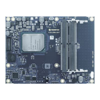
Figure 1: Come-Bdv7 COM Express® Module
13
Product Naming Clarification
14
COM Express® Documentation
14
COM Express® Functionality
15
COM Express® Benefits
15
Table 1: Pin Assignment of Type 6 and Come-Bdv7
15
2 / Product Specification
16
Module Variants
16
Commercial Grade Modules (0°C to +60°C)
16
Industrial Temperature Grade Modules (E2, -40°C to +85°C)
16
Rapid Shutdown Industrial Temperature Grade Modules (R E2, -40°C to +85°C)
16
Table 2: Product Number for Commercial Grade Modules (0°C to +60°C Operating)
16
Table 3: Product Number for Industrial Grade Modules (-40°C to +85°C Operating)
16
Accessories
17
Table 4: Product Accessories
17
Table 5: Come Pin-Out Type 7 Accessories
17
Table 6: Memory Modules
17
3 / Functional Specification
19
Block Diagram
19
Figure 2: Block Diagram Come-Bdv7
19
Processor
20
Table 7: Intel® Denverton-NS- Atom® Processor Specifications Commercial Temperature
20
Table 8: Intel® Denverton-NS- Atom® Processor Specifications Industrial Temperature
21
System on a Chip (Soc)
22
System Memory
22
Usb
23
Usb 3.0
23
Usb 2.0
23
Sata
24
PCI Express (PCIE) Configuration
24
Ethernet
25
Quad Ethernet Ports with up to 10Gb
25
On-Board Gigabit Ethernet (1Gbe)
26
Soc High-Speed Interfaces Overview
27
Storage
28
Bios/Software
28
Come Features
28
Kontron Features
28
4 / Electrical Specification
29
Power Supply Specifications
29
Power Supply Voltage Rise Time
29
Power Supply Voltage Ripple
29
Inrush Current
29
Power Management
29
Power Supply Control Settings
30
Power Supply Modes
30
5 / Thermal Management
32
Heatspreader and Active or Passive Cooling Solutions
32
Active or Passive Cooling Solutions
32
Operating with Kontron Heatspreader Plate (HSP) Assembly
32
Operating Without Kontron Heatspreader Plate (HSP) Assembly
32
Table 9: Heatspreader Test Temperature Specifications
32
On-Board Fan Connector
33
Table 10: Fan Connector (3-Pin) Pin Assignment
33
Table 11: Electrical Characteristics of the Fan Connector
33
Figure 3: Fan Connector 3-Pin
33
6 / Environmental Specification
34
Temperature
34
Humidity
34
Table 12: Temperature Grade Specifications
34
Table 13: Humidity Specification
34
7 / Standards and Certification
35
Table 14: Standards and Certification Compliance
35
8 / Mechanical Specification
36
Dimensions
36
Height
36
Figure 4: Module Dimensions
36
Figure 5: Module and Carrier Height
36
Module Height with Four SODIMM Memory Sockets
37
Figure 6: Module Top and Bottom SODIMM Assembly (Option)
37
Heatspreader Dimensions
38
Figure 7: Heatspreader Dimension
38
9 / Features and Interfaces
39
ACPI Power States
39
Emmc
39
Table 15: Supported Power States Function
39
Fast I2C
40
Gpio
40
Hwm
40
Hyper Threading
40
Lpc
41
Radid Shutdown
41
Table 16: Supported BIOS Features
41
Crowbar
42
Rtc
42
Security Solution (APPROTECT)
42
Smbus
42
Speedstep® Technology
42
Spi
43
SPI Boot
43
Table 17: SPI Boot Configuration
43
Table 18: Supported SPI Boot Flash Types for 8-SOIC Package
43
Module SPI Flash Chips
44
Using an External SPI Flash
44
External SPI Flash on Modules with Intel® ME
45
Tpm 2.0
45
Uart
45
Watchdog Timer - Dual Stage
45
Table 19: Dual Stage Watchdog Timer- Time-Out Events
45
WDT Signal
46
XDP (Option)
46
10 / System Resources
47
Legacy Interrupt Request (IRQ) Lines
47
Memory Area
47
Table 20: Legacy IRQ Lines
47
Table 21: Designated Memory Locations
47
I/O Address Map
48
Table 22: Designated I/O Port Address Ranges
48
Peripheral Component Interconnect (PCI) Devices
50
I2C Bus
50
Table 23: I2C Bus Port Addresses
50
System Management (Smbus)
51
Table 24: Smbus Addresses
51
11 / Come Connector
52
Figure 8: Come Connector with 220 Pins
52
Figure 9: X1A and X1B Come Interface Connectors
52
X1A and X1B Come Interface Connector Signals
53
Come Connector (X1A and X1B) Pin Assignment
53
Table 25: General Signal Description
53
Table 26: X1A Connector Pin Assignment Row (A1-A110)
53
Table 27: X1A Connector Pin Assignment Row (B1-B110)
53
Table 28: X1B Connector Pin Assignment Row (C1-C110)
53
Table 29: X1B Connector Pin Assignment Row (D1-D110)
53
Connector X1A Row A1 - A110
54
Connector X1A Row B1 - B100
57
Connector X1B Row C1 - C110
60
Connector X1B Row D1 - D110
63
12 / Uefi BIOS
66
Starting the Uefi BIOS
66
Table 30: Navigation Hot Keys Available in the Legend Bar
66
Setup Menus
68
Main Menu
68
Figure 10: Setup Menu Selection Bar
68
Figure 11: Main Setup Menu
68
Table 31: Main Setup Menu Functions
69
Advanced Menu
70
Table 32: Advanced Setup Menu Functions
70
Figure 12: Advanced Setup Menu
70
Table 33: Interlrcsetup Setup Menu Functions
79
Figure 13: Intelrcsetup
79
Table 34: Security Setup Menu Functions
93
Figure 14: Security Setup Menu
93
Table 35: Boot Setup Menu Functions
95
Figure 15: Boot Setup Menu
95
Save and Exit
96
Table 36: Save and Exit Menu Functions
96
Figure 16: Save and Exit Setup Menu
96
Basic Operation of the Uefi Shell
97
Appendix A: List of Acronyms
98
Table 37: List of Acronyms
98
Advertisement
Advertisement
Related Products
Kontron COMe-cHL6
Kontron COMe-m4AL10
Kontron COMe-cDV7
Kontron CP305
Kontron CP6001-R3
Kontron coolMONSTER/S
Kontron coolMONSTER/P3
Kontron coolMONSTER/C3
Kontron COMe-bP5020
Kontron COMe-bIP6RXT
Kontron Categories
Computer Hardware
Motherboard
Server
Industrial PC
Desktop
More Kontron Manuals
Login
Sign In
OR
Sign in with Facebook
Sign in with Google
Upload manual
Upload from disk
Upload from URL