Sign In
Upload
Manuals
Brands
Kontron Manuals
Motherboard
AdvancedTCA AT8050
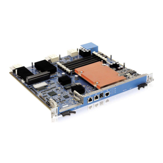
Kontron AdvancedTCA AT8050 Manuals
Manuals and User Guides for Kontron AdvancedTCA AT8050. We have
1
Kontron AdvancedTCA AT8050 manual available for free PDF download: User Manual
Kontron AdvancedTCA AT8050 User Manual (165 pages)
Brand:
Kontron
| Category:
Motherboard
| Size: 6 MB
Table of Contents
Customer Service
2
Revision History
2
Table of Contents
3
Safety Instructions
10
Before You Begin
10
Preventing Electrostatic Discharge
11
Preface
12
How to Use this Guide
12
Customer Comments
13
Advisory Conventions
13
Unpacking
14
Powering up the System
14
Adapter Cables
14
Storing Boards
14
Regulatory Compliance Statements
15
Safety Certification
15
Limited Warranty
16
Chapter 1
18
Product Description
18
Product Overview
18
What's Included
18
Board Specifications
19
Table 1-1 Board Specifications
19
Compliance
21
Hot-Plug Capability
21
Interfacing with the Environment
21
RTM (Rear Transition Module)
21
Advanced Mezzanine Card
23
Chapter 2
25
Board Features
25
Block Diagram
25
Figure 2-1:Block Diagram
25
System Core
26
Processor
26
Intel IOH 36D
26
Ich10R
26
USB 2.0 Interfaces
27
Table 2-1 USB Connector Pinout
27
Serial Ata/Serial Attached SCSI
28
Serial Attached SCSI (Lsisas1064E Is PCI-E Rev 1.1)
28
Serial ATA (ICH10R)
29
USB Flash Module
28
Update Channel
29
Real Time Clock & NVRAM
29
Redundant BIOS Flash
29
Ethernet Interfaces
30
Fabric Interface
30
Base Interface
31
Management Interface
31
Ethernet Interfaces Configuration
32
Figure 2-2:Available Ethernet Interfaces Configurations
32
Figure 2-3: 10Gbe and Management to Front Panel
33
Figure 2-4: 10Gbe and Management to AMC
34
Figure 2-5: 10Gbe and Management to RTM
35
Figure 2-6: AMC to Fabric Interface and Management to Front Panel
36
Figure 2-7: AMC to Fabric Interface and Management to AMC
37
Figure 2-8: AMC to Fabric Interface and Management to RTM
38
Figure 2-9: Management to Fabric Interface
39
2.10 Serial Interfaces
40
2.11 AMC Mezzanine
40
Table 2-2 Serial Interface Connector Pinout
40
Bios Settings
41
2.12 Fpga
42
2.13 Telecom Clock Option
42
2.14 Redundant IPMC Firmware & Bootblock
42
2.15 Leds Description
43
Hot Swap LED (LED0)
43
Out of Service (LED1)
43
Healthy LED (LED2)
43
Table 2-3 Faceplate Leds
43
Figure 2-10: Faceplate Leds
44
Chapter 3
46
Installing the Board
46
Setting Jumpers
46
Jumper Description
46
Setting Jumper & Locations
46
Figure 3-1: Jumper Settings and Locations
46
Table 3-1 Jumper Description
46
Processor
47
Memory
47
Memory List and Characteristics
48
Table 3-2 Approved Memory List
48
Installing Memory
49
Onboard Connectors and Headers
50
Figure 3-2:Onboard Connectors and Headers Locations
50
Table 3-3 Onboard Connectors and Headers
50
Board Hot Swap and Installation
51
Installing the Board in the Chassis
51
Removing the Board
51
Installing an AMC
52
Removing an AMC
52
Installing the RTM8050
52
Removing the RTM8050
52
Hardware Management
54
Hardware Management Overview
54
Hardware Management Functionality
54
IPMC Specific Features
54
Sensors
55
Ipmc
56
Supported Commands
56
Table 4-1 IPM Device Supported Commands for IPMC
56
Table 4-2 Watchdog Timer Supported Commands for IPMC
56
Table 4-3 Device Messaging Supported Commands for IPMC
56
Table 4-4 Chassis Device Supported Commands for IPMC
58
Table 4-5 Event Supported Commands for IPMC
58
Table 4-6 PEF and Alerting Supported Commands for IPMC
59
Table 4-7 Sensor Device Supported Commands for IPMC
59
Table 4-8 FRU Device Supported Commands for IPMC
60
Table 4-9 SDR Device Supported Commands for IPMC
60
Table 4-10 SEL Device Supported Commands for IPMC
60
Table 4-11 LAN Device Supported Commands for IPMC
61
Table 4-12 Serial/Modem Device Supported Commands for IPMC
61
Table 4-13 SOL Commands
62
Table 4-14 PICMG 3.0 Commands for IPMC
62
Table 4-15 AMC.0 Carrier Commands for IPMC
63
Sensor Data Records
64
Table 4-16 HPM Commands
64
Table 4-17 IPMC Sensors
65
Table 4-18 IPMC Health Indicator Sensor Aggregation Table
72
FRU Information
74
Table 4-19 Board Information Area
74
Table 4-20 Product Information Area
75
Table 4-21 E-Keying Capabilities of the Board
76
Table 4-22 AMC Carrier Activation and Carrier Information Table
77
Table 4-23 Carrier AMC.0
78
Table 4-24 Mapping between the Devices and the Corresponding Ids
78
Table 4-25 Record's Content
78
Table 4-26 AMC Connectivity Details for "Intel IOH PCI-Express Root Complex Port 3
82
Table 4-27 AMC Connectivity Details for "Intel IOH PCI-Express Root Complex Port 8
84
Table 4-28 AMC Connectivity Details for "Intel ICH10 SATA Controller
86
Table 4-29 AMC Connectivity Details for "Intel 82576EB NC (Front/Rear)
87
Table 4-30 AMC Connectivity Details for "Onboard Fabric Channel 1 Switch
88
Table 4-31 AMC Connectivity Details for "Onboard Fabric Channel 2 Switch
89
Table 4-32 AMC Connectivity Details for "FPGA Based UART
90
Clock E-Keying Information
91
Table 4-33 Clock Resources ID Assignment Mapping
91
Table 4-34 Carrier Clock Point-To-Point Connectivity Record Table
91
Table 4-35 Pcie Clock Generator
93
Table 4-36 Onboard Clock Multiplexer
94
Component Upgrade Support
98
Table 4-37 HPM Component Ids
98
Table 4-38 Non-HPM Components
98
Software Setup
100
AMI BIOS Setup Program
100
Accessing the BIOS Setup Utility
100
Menu Bar
102
Main Menu
103
Advanced Menu
104
Security Menu
114
Boot Menu
115
System Management Menu
120
Exit Menu
129
Boot Utilities
129
Entering BIOS Setup Menu
129
Boot Menu POP-UP
129
SAS Option ROM
129
BOOT Menu POP-UP
130
Console Redirection (VT100 Mode)
130
Requirements
130
ANSI and VT100 Keystroke Mapping
130
VT-UTF8 Keystroke Mapping
131
Thermal Considerations
133
Thermal Monitoring
133
Heat Sinks
133
Temperature Sensors
133
Table 6-1 Temperature Sensors Thresholds
134
Airflow Blockers
135
System Airflow
135
Figure 6-1:Pressure Curve in Imperial
135
Table 6-2 Pressure Curve AT8050 with AMC Filler
135
Thermal Profile
136
Figure 6-2:Pressure Curve in Metric
136
Figure 6-3:CPU Thermal Profile
136
Memory & I/O Maps
137
Memory Mapping
137
Kontron I/O Mapping
138
PCI IDSEL and Device Numbers
139
Telco Clock
141
Connector Pinouts
147
Connectors and Headers Summary
147
Post Codes (J2
147
Amc B1(J5
148
Ethernet(J8 & J9
149
USB Port (J10
149
Serial Port, COM1(J12
149
Synchronisation Clocks, Update Channel (J20
150
USB Flash Drive(J22
150
Base Interface & Fabric Intercface (J23
151
RTM Connector (J30
152
Power (P10
153
BIOS Setup Error Codes
154
Bootblock Initialization Code Checkpoints
154
POST Code Checkpoints
155
DIM Code Checkpoints
157
Memory Initialization ERROR Code
158
Software Update
159
Getting Help
160
Returning Defective Merchandise
160
When Returning a Unit
161
Glossary
162
Advertisement
Advertisement
Related Products
Kontron ATX-KBL-S
Kontron ATX-HSW-S
Kontron AdvancedTCA Series
Kontron AT8060
Kontron AT8901
Kontron AT8402
Kontron AdvancedTCA AT8901M
Kontron AT8902M
Kontron AdvancedTCA AT8001
Kontron AM4100
Kontron Categories
Computer Hardware
Motherboard
Server
Industrial PC
Desktop
More Kontron Manuals
Login
Sign In
OR
Sign in with Facebook
Sign in with Google
Upload manual
Upload from disk
Upload from URL