Sign In
Upload
Manuals
Brands
Kongsberg Manuals
Marine Equipment
Seatex Seapath 200
Kongsberg Seatex Seapath 200 Manuals
Manuals and User Guides for Kongsberg Seatex Seapath 200. We have
1
Kongsberg Seatex Seapath 200 manual available for free PDF download: Installation Manual
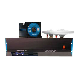
Kongsberg Seatex Seapath 200 Installation Manual (130 pages)
Motion Sensor
Brand:
Kongsberg
| Category:
Marine Equipment
| Size: 1.99 MB
Table of Contents
Table of Contents
7
1 Introduction
15
About this Manual
15
References
16
Definitions, Abbreviations and Acronyms
16
Definitions
16
Abbreviations and Acronyms
17
2 Specifications
19
Physical Dimensions
19
Power
20
Environmental Specification
20
Cable
21
3 Installation
23
General Information
23
Logistics
24
Location of the System Parts
25
The GPS Antennas
25
The MRU 5
26
The Processing Unit
27
The Video Display Unit
27
Procedures
27
Mechanical Installation
27
Installation Procedure
28
Figure 1 Dimensional Drawing for the Antenna Holder
28
Figure 2 Top View of the Antenna Bracket
28
Figure 3 the Different Components for Mounting of the Antenna Bracket
29
Figure 4 Side View of the GPS Antenna Installation
29
Figure 5 Recommended Orientation of the MRU Mounting Bracket
30
Figure 6 Wall Mounting of Bracket with MRU Connector Pointing down
30
Figure 7 Sticker (4) Shall Indicate Actual Mounting Orientation of MRU Within Bracket
31
Figure 8 Junction Box Mounting
32
Figure 9 Connection Box Mounting
32
Electrical Installation
33
Figure 10 Rear Panel of the Processing Unit
33
MRU to Processing Unit Cable Wiring
34
External Input and Output Serial Lines
35
1PPS Signal Connection
37
Ethernet Connection
37
Analog Output
38
Installation Procedure
39
Setup of Configuration Parameters
41
Lever Arm Vector Determinations
41
Input Data
42
Figure 11 the Offset Vectors between the Different Components
42
Serial Data Output
43
Setup Procedure
44
Calibration
44
Calibration of the GPS Antenna Installation
44
Typical Calibration Procedure
45
Figure 12 GPS Antenna Configuration
46
Figure 13 Page 1 of GPS Antenna Calibration
46
Figure 14 Page 2 of GPS Antenna Calibration
47
Figure 15 Page 3 of GPS Antenna Configuration
48
Calibration of MRU Axis
49
Figure 16 Page 4 of GPS Antenna Configuration
49
Figure 17 Value of Roll-Error as Function of Vessel Pitch Angle as Parameter and 1° and
50
4 Installation Drawings
51
5 Appendix A - Installation Worksheet
59
6 Appendix B - Output Protocols from Seapath
65
NMEA Format
65
Binary Format 3
67
Binary Format, Simrad EM1000/950 Compatible
68
Binary Format, Simrad EM3000, EM300 and Hipap Compatible
69
Calibration Format
70
Echo Sounder Format 9
70
RDI ADCP Format
71
Binary Format 11
71
Lehmkuhl Gyro Repeater Format
73
1PPS Time Tag, NMEA ZDA Message
73
1PPS Time Tag, Trimble Compatible
73
Atlas Fansweep Format
74
Echo Sounder Format 18
75
Submetrix Format
75
Cyclic Redundancy Check Algorithm
77
7 Appendix C - Installation of Coax Connectors on Superflex Cable
79
7. Appendix C - Installation of Coax Connectors on Superflex
85
8 Appendix D - Seapath Configuration Software, Scc
85
Software Installation
85
Figure 18 Installation Complete
85
How to Get Started
86
Starting the Program
86
Figure 19 SCC Start Window
86
Figure 20 Initial Offline Dialog
87
Figure 21 Seapath Control Centre, Main Window
87
Setting the Serial Port Parameters
88
Establishing Connection
88
Figure 22 Communication Setup
88
Figure 23 Connect Status
89
Figure 24 Connected to Seapath
89
General User Interface
90
File Menu
90
Demo
90
Exit
90
Wizards Menu
91
View Menu
91
Figure 25 Setup Icons
91
Help Menu
92
Tool Buttons
92
Figure 26 about SCC
92
Figure 27 Tool Buttons
92
Seapath Control Centre Button
93
Figure 28 Keep Folder List Open
93
Figure 29 Close Folder List
93
Figure 30 Vessel 3D-View, Ghost Mode
93
Mouse Operation
94
Figure 31 Vessel Drop down Menu
94
Editing Parameter Values
95
Vessel Settings
95
Vessel Geometry
95
Vessel Description
96
Figure 32 Vessel Geometry
96
Figure 33 Vessel Description
96
GPS Sensor Settings
97
GPS Geometry
97
GPS Processing
97
Figure 34 GPS Geometry
97
Figure 35 GPS Processing Settings
98
GPS Reference Stations
99
SBAS Common Settings
99
Figure 36 GPS Reference Stations
99
GPS Antenna Configuration
100
Figure 37 SBAS Common Settings for WAAS Satellites
100
Figure 38 GPS Antenna Configuration
101
Figure 39 Page 1 of GPS Antenna Calibration
101
Figure 40 Page 2 of GPS Antenna Calibration
102
Figure 41 Stop Antenna Calibration
103
Figure 42 Page 3 of GPS Antenna Configuration
103
Figure 43 Edit Calibration Data
104
GPS Attitude Processing
105
Figure 44 Page 4 of GPS Antenna Configuration
105
Figure 45 GPS Attitude Processing
105
MRU Sensor Settings
106
MRU Geometry
106
Figure 46 MRU Geometry
106
Figure 47 Step 1 of MRU Axis Orientation
107
Figure 48 Step 2 of Manual MRU Axis Orientation
107
Figure 49 Step 3 of Manual MRU Axis Orientation
108
Figure 50 Positive Offset Angles Rotations
109
Figure 51 Step 2 of Auto MRU Axis Orientation
109
Figure 52 Step 3 of Auto MRU Axis Orientation
110
MRU Heave Configuration
111
Measurement Points
112
Measurement Points Geometry
112
Figure 53 MRU Heave Filter
112
Data Interface
113
Host Common
113
Figure 54 Measurement Points Geometry
113
Network Common
114
Figure 55 Common Host Settings
114
Input
115
Figure 56 Common Network Settings
115
Figure 57 Data Interface - Input Configuration
115
Figure 58 Serial Port Setting
116
Figure 59 Format Setting
116
Output
117
Figure 60 RTCM Format Decoding
117
Figure 61 Formats Available for Device Type Gyro
117
Figure 62 Data Interface - Output Configuration
118
Figure 63 Network Settings
118
Figure 64 Analog Settings
119
Figure 65 Measurement Point
119
Figure 66 Message Interval Settings
119
Figure 67 Selection of NMEA Output Standard
120
Figure 68 Format Settings
120
Figure 69 Analog Format Settings
121
Figure 70 Datawell Hippy Compatible Analog Output Signals
121
Parameter Management
122
Download
122
Figure 71 Input of Test Voltage for the Selected Analog Channel
122
Figure 72 Download Parameters
122
Upload
123
Save on File
123
Figure 73 Upload Parameters
123
Figure 74 Save on File
123
Load from File
124
Undo
124
Figure 75 Load from File
124
Figure 76 Undo
124
Generate Report
125
Figure 77 Generate Configuration Report
125
Figure 78 Configuration Report
125
Index
127
Reader's Comments
129
Advertisement
Advertisement
Related Products
Kongsberg SIMRAD 22092100
Kongsberg SIMRAD 22092142
Kongsberg SIMRAD 22092456
Kongsberg 315089
Kongsberg 315126
Kongsberg AI70 Automatic
Kongsberg AI71
Kongsberg APOS Survey
Kongsberg EA 400
Kongsberg EA 600
Kongsberg Categories
Marine Equipment
Sonar
Marine Radio
Transceiver
Radio
More Kongsberg Manuals
Login
Sign In
OR
Sign in with Facebook
Sign in with Google
Upload manual
Upload from disk
Upload from URL