Sign In
Upload
Manuals
Brands
Klein Marine Systems, Inc. Manuals
Sonar
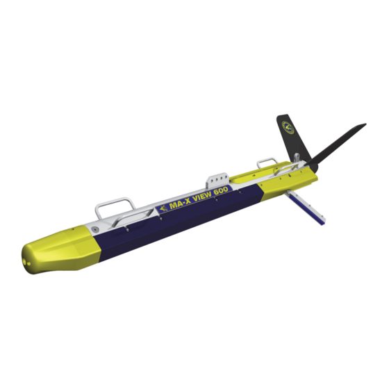
MA-X VIEW 600
Klein Marine Systems, Inc. MA-X VIEW 600 Manuals
Manuals and User Guides for Klein Marine Systems, Inc. MA-X VIEW 600. We have
1
Klein Marine Systems, Inc. MA-X VIEW 600 manual available for free PDF download: Operation And Maintenance Manual
Klein Marine Systems, Inc. MA-X VIEW 600 Operation And Maintenance Manual (128 pages)
Brand:
Klein Marine Systems, Inc.
| Category:
Sonar
| Size: 35 MB
Table of Contents
Table of Contents
4
List of Figures
8
Sonar System Warranty
11
What Is Covered
11
Conditions of Warranty
12
Changes, Errors and Omissions
13
Software License Agreement
14
Preface
16
What's in this Manual
16
Note, Warning and Caution Notices
17
Customer Service and Technical Support
18
CHAPTER 1: Overview
19
Equipment
19
Main Features
19
Splashproof Transceiver and Processing Unit
20
(Sp-III Tpu)
20
Towfish
20
Figure 1-1: Towfish
21
Laptop Computer
22
Rack Mount Transceiver and Processing Unit (Rack Mount TPU)
22
Sonarpro Workstation
23
Tow Cable
24
CHAPTER 2 Specifications
26
Sp-III Tpu
26
Rack Mount TPU
26
Laptop Computer
26
Sonarpro Workstation
27
Towfish
27
General
27
Sensors
28
Tow Cables
28
Lightweight Coaxial Tow Cable
28
Armored Coaxial Tow Cable (0.322-Inch)
29
Armored Coaxial Tow Cable (0.40-Inch)
29
CHAPTER 3: Setup and Test
31
Unpacking and Inspection
31
Locating the Topside System Components
32
Power Requirements
32
Table 3-1: Power Cord Wiring
32
Figure 3-1: SP-III TPU Side Panel
36
Rack Mount TPU Connections
37
Connecting the SP-III TPU and the Laptop Computer
39
Connecting the Topside System Components
39
Sonarpro Workstation Connections
39
Attaching the Stabilizer Fins
33
Breakers
33
Grounding
33
Rack Mount TPU and Sonarpro Workstation Circuit
33
Towfish Setup
33
Connecting the Tow Cable to the Towfish
34
Disconnecting the Tow Cable from the Towfish
34
SP-III TPU Connections
35
Topside System Connections
35
Figure 3-3: Sonarpro Workstation Back Panel
40
Table 3-2: Towfish Jumper Cable Connector Pinout
41
Table 3-5: 120/240 VAC Connector Pinouts
42
Table 3-6: TOWFISH Connector Pinouts
42
Table 3-8: T/F TRIG, RESP TRIG, 1PPS, and EXG TRIG in Pinouts
42
Table 3-3: LAN Connector Pinouts
42
Figure 3-4: Rack Mount TPU Front Panel
46
Figure 3-5: Sonarpro Workstation Front Panel
49
Activating and Testing the System at Sea
51
Table 3-7: NAV, DEBUG and MAG Connector Pinouts
42
Activating and Testing the System on Deck
48
Sonarpro Workstation Controls and Indicators
48
System Activation and Test
48
Table 3-4: 12 VDC Connector Pinouts
42
Connecting the Rack Mount TPU and the Sonarpro Workstation
43
Rack Mount TPU Controls and Indicators
45
SP-III TPU Controls and Indicators
45
Topside System Controls and Indicators
45
Figure 3-6: Towfish with Gap-Filling Transducers Deployed
53
CHAPTER 4: Equipment Maintenance
55
Daily Maintenance Checklist
55
Maintenance Checklists
55
Maintenance General Comments
55
Long Term Maintenance Checklist
56
Weekly Maintenance Checklist
56
Disassembling and Reassembling the Towfish
57
Disassembling the Towfish
57
Figure 4-1: Loosening the Tail Cone Retaining Bolt
57
Figure 4-2: Removing the Tail Cone
58
Figure 4-8: Pulling the Forward End Cap out of the Towfish Housing
61
Figure 4-11: Pulling the Electronics Chassis out of the Towfish Housing
62
Figure 4-10: Tightening the Locking Screws in the Towfish Housing Aft End Cap
62
Figure 4-12: Transition Board
63
Figure 4-20: Disconnecting the Gap-Filling Transducer Connector
67
Installing the Gap-Filling Transducers
70
Removing the Skid Plate
65
Installing the Side Scan Transducers
66
Removing the Side Scan Transducers
66
Removing the Gap-Filling Transducers
67
Figure 4-9: Forward End Cap Removed from the Towfish Housing
61
Reassembling the Towfish
63
Figure 4-19: Removing the Seven Socket Head Cap Screws Securing the Gap-Filling
67
CHAPTER 5: Technical Description
71
Sonar Electronics
71
Towfish
71
Figure 5-1: the MA-X View 600 Sonar System Towfish Electronics Block Diagram
72
Transducer Arrays
75
Sp-III Tpu
76
Figure 5-3: SP-III TPU Electronics Block Diagram
77
Figure 5-4: SP-III TPU Electronics
78
Rack Mount TPU
79
Figure 5-5: the MA-X View 600 Sonar System Rack Mount TPU Electronics Block
80
APPENDIX A: Notes on Handling Tow Cables
83
A.1 Unreeling Tow Cable
83
Figure A-1: Correct Methods to Unreel Tow Cable
83
Figure A-2: Spooling Real to Drum
84
A.3.2 Effect of Cable Kinking
85
A.3.3 Result of Cable Kinking
85
A.2 Uncoiling Tow Cable
84
A.3 Cable Kinking
84
A.3.1 Cause of Cable Kinking
84
Figure A-3: Cable Loop and Kink
85
Figure A-4: Damaged Cable
85
APPENDIX B: Configuring and Updating the SP-III TPU
87
B.1 Starting Linux TPU Updater
87
B.2 Querying or Changing the SP-III TPU IP Address
88
Figure B-2: the Select RS-232 Port Dialog Box
88
Figure B-3: the Klein Linux TPU Updater Dialog Box with Current TPU IP
89
B.4 Updating the SP-III TPU Software
90
B.3 Editing the SP-III TPU Startup File
89
APPENDIX C: Compass Calibration
93
C.1 Overview
93
C.2 Required Items
93
Procedure
93
Table C-1: ICCSTAT Result Codes
95
APPENDIX D: Rigging Guide
97
APPENDIX E: Drawings
101
Appendix F:towfish Towing Characteristics
107
APPENDIX G: System Setup Diagram with Acoustic Positioning
127
System
127
Diagram
127
Figure
128
System Setup Diagram with Towfish, Navigation, Acoustic Positioning System, and Laptop Computer Connections
128
Advertisement
Advertisement
Related Products
Klein Marine Systems, Inc. HYDROCHART 3500
Klein Marine Systems, Inc. HydroChart 5000
Klein Marine Systems, Inc. Categories
Sonar
More Klein Marine Systems, Inc. Manuals
Login
Sign In
OR
Sign in with Facebook
Sign in with Google
Upload manual
Upload from disk
Upload from URL