
Related Manuals for Klein Marine Systems, Inc. MA-X VIEW 600


Summary of Contents for Klein Marine Systems, Inc. MA-X VIEW 600
- Page 1 MA-X V 600 S ONAR YSTEM Operations and Maintenance Manual , Rev. 00 11210097 11 Klein Drive Salem, NH 03079-1249 U.S.A. Tel: (603) 893-6131 Fax: (603) 893-8807 www.KleinMarineSystems.com...
- Page 2 Pentium are registered trademarks of Intel Corporation. ® Windows is a registered trademark of Microsoft Corporation. ® Kevlar is a registered trademark of the DuPont Company. MA-X View 600 Sonar System Operations and Maintenance Manual P/N 11210097, Rev. 00...
- Page 3 WARNING Klein Marine Systems, Inc. recommends all troubleshooting be done by a trained technician. Some circuits in the Sonar Transceiver and Processing Unit have voltages as high as 240 volts, and some circuits in the sonar towfish have 1500 volts. You should familiarize yourself with the location of these voltages before you attempt any troubleshooting.
-
Page 4: Table Of Contents
SonarPro Workstation ....... . 2-3 MA-X View 600 Sonar System Operations and Maintenance Manual P/N 11210097, Rev. 00... - Page 5 Towfish ......... . . 2-3 2.6.1 General .
- Page 6 Updating the SP-III TPU Software ..... . B-4 MA-X View 600 Sonar System Operations and Maintenance Manual P/N 11210097, Rev. 00...
- Page 7 APPENDIX C: Compass Calibration ......C-1 Overview ......... . C-1 Required Items .
-
Page 8: List Of Figures
The Three Screws Securing the Skid Plate to the Towfish ... . . 4-11 Figure 4-16: Removing the Three Screws Securing the Skid Plate to the Towfish ..4-11 MA-X View 600 Sonar System Operations and Maintenance Manual P/N 11210097, Rev. 00... - Page 9 Figure 5-1: Figure 5-2: The MA-X View 600 Sonar System Towfish Electronics Chassis ..5-3 Figure 5-3: SP-III TPU Electronics Block Diagram ......5-7 Figure 5-4: SP-III TPU Electronics .
- Page 10 ICCSTAT Result Codes ......... . . C-3 MA-X View 600 Sonar System Operations and Maintenance Manual P/N 11210097, Rev. 00...
-
Page 11: Sonar System Warranty
During the warranty period, Seller will repair or, at its option, replace any equipment that proves to be defective. Such repair or replacement is Buyer’s exclusive right and remedy, and our only obligation, with respect to any defective equipment. MA-X View 600 Sonar System Operations and Maintenance Manual P/N 11210097, Rev. 00... -
Page 12: Conditions Of Warranty
Conditions Of Warranty a) Seller’s warranty policy does not apply to equipment which has been subjected to accident, abuse, or misuse, shipping damage, alterations, incorrect and/or non- authorized service or equipment on which the serial number plate has been altered, mutilated or removed. b) A suitable proof of purchase, such as, a paid commercial invoice, an installation certificate signed by Seller or an authorized agent must be made available to Seller or Seller’s authorized servicing agent at the time of the Warranty Service. -
Page 13: Changes, Errors And Omissions
In addition, while considerable effort has been made to ensure that the information in this manual is accurate and complete, Klein Marine Systems, Inc. assumes no liability for any errors or omissions. MA-X View 600 Sonar System Operations and Maintenance Manual P/N 11210097, Rev. 00... -
Page 14: Software License Agreement
Software is used only in connection with one KMS Series 3000, UUV-3500, 3900, 4900, 5000, 5000 V2, 5900, HydroChart 3500, HydroChart 5000, D3500TF, or MA-X View 600 Sonar System. You may reproduce and provide authorized copies only of the Software and supporting documentation for each such workstation or network server for this equipment on which the Software is used as permitted hereunder. - Page 15 MA-X View 600 Sonar System Operations and Maintenance Manual P/N 11210097, Rev. 00...
-
Page 16: Preface
Software, and may be amended only in a writing signed by both parties. Preface The MA-X View 600 Sonar System is a towed single beam sonar comprising a towed underwater vehicle and topside equipment. What’s in This Manual... -
Page 17: Note, Warning And Caution Notices
WARNING Identifies a potential hazard that could cause personal injury or death to yourself or to others. CAUTION Identifies a potential hazard that could be damaging to equipment or could result in the loss of data. MA-X View 600 Sonar System Operations and Maintenance Manual P/N 11210097, Rev. 00... -
Page 18: Customer Service And Technical Support
xviii Customer Service and Technical Support To order spares or replacement parts or for any non-technical questions, contact KMS customer service. For answers to technical questions, contact KMS technical support. Customer service and technical support can be contacted using any of the following means: Mail Klein Marine Systems, Inc. -
Page 19: Chapter 1: Overview
CHAPTER 1: O VERVIEW The MA-X View 600 Sonar System is a combined side scan and nadir gap-filling, very high resolution, single beam side scan sonar system that is ideally suited for search and recovery (SAR) missions and coastal surveys requiring high accuracy in shallow water environments. -
Page 20: Towfish
The SP-III TPU is powered from either an AC or DC power source. CAUTION Do not submerge the SP-III TPU in water, as it is not designed for continuous immersion. MA-X View 600 Sonar System Operations and Maintenance Manual P/N 11210097, Rev. 00... -
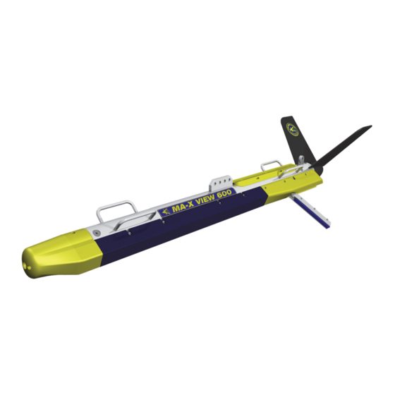
Page 21: Figure 1-1: Towfish
Stabilizing fins Safety cable tab Jumper cable Tow bracket Carrying Tail cone handle (4) Port gap-filling transducer Stainless steel housing Port side scan transducer Nose cone Figure 1-1: Towfish... -
Page 22: Laptop Computer
GPS, and a 1PPS input is provided which inputs 1PPS (one pulse per second) signals from the GPS. This signal is MA-X View 600 Sonar System Operations and Maintenance Manual P/N 11210097, Rev. 00... -
Page 23: Sonarpro Workstation
Equipment used in conjunction with a NMEA $ZDA message input to add an accurate time stamp to the data. The TPU provides power and downlink commands to the towfish by combining 200 VDC with FSK control signals for transmission over the coaxial conductor in the tow cable. -
Page 24: Tow Cable
SP-III TPU to the towfish, and to transmit sonar and sensor data from the towfish to the SP-III TPU. Cable lengths longer than 50 meters are available. MA-X View 600 Sonar System Operations and Maintenance Manual P/N 11210097, Rev. 00... - Page 25 CHAPTER 2: S PECIFICATIONS This chapter includes the physical and performance specifications for the main components of the MA-X View 600 Sonar System. NOTE Specifications are typical and subject to change without notice. Sonar System 1 port and 1 starboard side scan; 1 port...
-
Page 26: Chapter 2 Specifications
39.0 cm (15.6 in.) wide Size: 3.8 cm (1.5 in.) high 30.0 cm (11.8 in.) deep Weight: 3.2 kg (7.0 lb) Windows Operating system: SonarPro Applications software: MA-X View 600 Sonar System Operations and Maintenance Manual P/N 11210097, Rev. 00... -
Page 27: Sonarpro Workstation
SonarPro Workstation SonarPro Workstation 8.9 cm (3.5 in.) H Size: 48.3 cm (19.0 in.) W 43.2 cm (17.0 in.) D 22.8 kg (50 lb) Weight: 2U, 19-inch rack mount Chassis type: Intel Pentium Dual Core CPU: 8 GB Memory: SATA hard drive Storage: DVDRW optical drive (2) Ethernet 10/100/1000baseT... -
Page 28: Sensors
1.156 cm (0.455 in.) Diameter (OD): 2270 kg (5000 lb) Breaking strength: 454 kg (1000 lb) Working load: Operational length: 300 m maximum 600 VDC Voltage rating: MA-X View 600 Sonar System Operations and Maintenance Manual P/N 11210097, Rev. 00... -
Page 29: Armored Coaxial Tow Cable (0.322-Inch)
Tow Cables 2.7.2 Armored Coaxial Tow Cable (0.322-inch) Double layer, counter helical, galvanized Type: improved plow steel (GIPS) Coaxial copper Conductors: 8.2 mm (0.322 in.) Diameter (OD): 42.7 kN (9600 lbf) Breaking strength: 10.7 kN (2400 lbf) Working load: 1500 m (4920 ft) maximum Operational length: 1200 VDC Voltage rating:... -
Page 31: Chapter 3: Setup And Test
CHAPTER 3: S ETUP AND This chapter provides instructions for unpacking the MA-X View 600 Sonar System, connecting its components and a navigation system, and testing the system both on deck and at sea. Descriptions of all the connections and the operator controls and indicators on the SP-III TPU and the Rack Mount TPU are also included. -
Page 32: Locating The Topside System Components
The Rack Mount TPU and the SonarPro Workstation require 100–125 or 200–250 VAC, 50–60 Hz power to operate. The MA-X View 600 Sonar System is designed to protect against over and under voltage and transient spikes. However, it is always best to check the power source carefully using a voltmeter or oscilloscope before operating the equipment. -
Page 33: Grounding
3.3.1 Grounding It is important that the MA-X View 600 Sonar System be well grounded to minimize potential hazards to the operator and electrical interference from other equipment. A good ground for the system is a low impedance, well conducted path to sea water. -
Page 34: Connecting The Tow Cable To The Towfish
“Topside System Controls and Indicators” on page 3-15. To disconnect the tow cable: Verify that the SP-III TPU or Rack Mount TPU is switched off and that its power cord is disconnected. MA-X View 600 Sonar System Operations and Maintenance Manual P/N 11210097, Rev. 00... -
Page 35: Topside System Connections
Topside System Connections Grasp the body of each connector at the towfish and gently pull them apart. Do not pull on the cables to separate the connectors. Always hold the body of the connectors. After separating the connectors, put a thin coating of silicone grease on the rubber section of the connector pins. -
Page 36: Figure 3-1: Sp-Iii Tpu Side Panel
D/C POLARITY NAV connector indicator T/F TRIG indicator LOCK LOSS DEBUG connector indicator T/F PWR RESP TRIG indicator MAG connector indicator indicator TOWFISH D/C-A/C connector switch 120/240 VAC connector T/F TRIG EXT TRIG IN 1PPS connector 12 VDC connector RESP TRIG connector connector connector... -
Page 37: Rack Mount Tpu Connections
Topside System Connections DB9 male RS-232 serial port connector that NAV: connects to a shipboard navigation system and inputs NMEA 0183 message sentence formats. The baud rate is 4800. 120/240 VAC: 3-pin bulkhead connector that connects to the AC power source. 4-pin bulkhead connector that connects to a 12 VDC 12 VDC: power source. - Page 38 LAN connector TRIG A connector T/F TRIG connector AC INPUT connector TOWFISH connector MAG connector NAV connector DEBUG 1PPS IN connector connector NOTE: Connectors that are not called out are not used or are for factory use only. Figure 3-2: Rack Mount TPU Back Panel...
-
Page 39: Sonarpro Workstation Connections
Connecting the Topside System Components Type N coaxial connector that connects to the TOWFISH: towfish or to the slip rings of the optional winch. IEC type connector that connects to the AC power AC INPUT: source. 3.5.3 SonarPro Workstation Connections All the connections to the SonarPro Workstation are made to connectors on the back panel which is shown in Figure 3-3. -
Page 40: Figure 3-3: Sonarpro Workstation Back Panel
AC INPUT connector ON/OFF switch DVI connector ETHERNET connector (2) and circuit breaker USB connector (4) NOTE: Connectors that are not called out are not used or are available for optional use. Figure 3-3: SonarPro Workstation Back Panel... -
Page 41: Table 3-2: Towfish Jumper Cable Connector Pinout
3-11 Connecting the Topside System Components For the connector pinouts and pin orientations for each of the connectors on the SP-III TPU side panel, refer to Table 3-3 through Table 3-8. For the connector pinout and orientation of the towfish jumper cable connector, refer to Table 3-2. Table 3-2: Towfish Jumper Cable Connector... -
Page 42: Table 3-3: Lan Connector Pinouts
12 VDC Table 3-3: Table 3-4: Connector Pinouts Connector Pinouts FUNCTION FUNCTION Return +12 VDC 120/240 VAC TOWFISH Table 3-5: Table 3-6: Connector Pinouts Connector Pinouts FUNCTION FUNCTION Neutral 200 VDC Power and Telemetry Shield Line Table 3-7: NAV, DEBUG Table 3-8: T/F TRIG, and MAG Connector... -
Page 43: Connecting The Rack Mount Tpu And The Sonarpro Workstation
3-13 Connecting the Topside System Components Connect the tow cable to the TOWFISH connector on the SP-III TPU. Connect the AC power cable to the 120/240 VAC connector on the SP-III TPU and to the AC power source, or connect the DC power cable to the 12 VDC connector on the SP-III TPU and to a 12 VDC power source, or both. - Page 44 A user supplied BNC-to-BNC cable is required. Connect the TRIG A connector on the Rack Mount TPU to the trigger input of a USBL system. A user supplied BNC-to-BNC cable is required. MA-X View 600 Sonar System Operations and Maintenance Manual P/N 11210097, Rev. 00...
-
Page 45: Topside System Controls And Indicators
3-15 Topside System Controls and Indicators Topside System Controls and Indicators The SP-III TPU includes controls and indicators on the side panel. The Rack Mount TPU and the SonarPro Workstation include controls and indicators on the front panels. The SonarPro Workstation also has its power switch on the back panel. -
Page 46: Figure 3-4: Rack Mount Tpu Front Panel
TOWFISH indicators STATUS indicators POWER indicator POWER switch EQUALIZATION indicators SYS READY indicator OPTIONS indicators T/F POWER indicator Figure 3-4: Rack Mount TPU Front Panel... - Page 47 3-17 Topside System Controls and Indicators Green LED that will flash while the Rack Mount SYS READY: TPU and the towfish are powering up and then remain on when the Rack Mount TPU is ready to link with SonarPro on the SonarPro Workstation. Blue LED that is on when power is being output to T/F POWER: the towfish.
-
Page 48: Sonarpro Workstation Controls And Indicators
RESET switch: Workstation. System Activation and Test The MA-X View 600 Sonar System should be activated and tested on deck and at sea before starting an actual survey. NOTE Should it be required to change the IP address, edit the startup.ini file or update the software of the SP-III TPU, refer to APPENDIX B: “Configuring and Updating the SP-III TPU”... -
Page 49: Figure 3-5: Sonarpro Workstation Front Panel
HARD DRIVE ACTIVITY indicator ETHERNET indicator POWER ON indicator DVDRW optical drive RESET switch POWER switch USB connector (2) Figure 3-5: SonarPro Workstation Front Panel... - Page 50 Also check that motion data are being displayed in the Information window. If a GPS is connected, check that navigation data are being displayed in the Information window. MA-X View 600 Sonar System Operations and Maintenance Manual P/N 11210097, Rev. 00...
-
Page 51: Activating And Testing The System At Sea
3-21 System Activation and Test Select the 50-m range and turn off the high frequency transmitter. Open the MA-X Viewer window to 50 percent and allow the TVG to normalize; it will take about two minutes. Perform a rub test on the port and starboard side scan transducers and the port and starboard gap-filling transducers to confirm that the receiver mode is operating properly. - Page 52 Refer to the SonarPro User Manual (P/N 11210093) for instructions on how to operate SonarPro to acquire, display and record sonar data. MA-X View 600 Sonar System Operations and Maintenance Manual P/N 11210097, Rev. 00...
-
Page 53: Figure 3-6: Towfish With Gap-Filling Transducers Deployed
Gap-filling transducers unfolded Figure 3-6: Towfish with Gap-filling Transducers Deployed... -
Page 55: Chapter 4: Equipment Maintenance
Maintenance General Comments Equipment used at sea is subjected to severe environmental and handling conditions. While the MA-X View 600 Sonar System is designed to operate in such conditions, a certain amount of routine maintenance is necessary to ensure trouble free, long term operation. -
Page 56: Weekly Maintenance Checklist
Follow the instructions in the manufacturer's manual for any necessary cleaning and maintenance of the laptop computer or the SonarPro Workstation. MA-X View 600 Sonar System Operations and Maintenance Manual P/N 11210097, Rev. 00... -
Page 57: Disassembling And Reassembling The Towfish
Disassembling and Reassembling the Towfish Disassembling and Reassembling the Towfish For troubleshooting purposes and for repair, it may be required to remove and replace major components of the towfish. Instructions are provided in the following pages for the disassembly of the towfish and the removal of the towfish electronics chassis and the transducers. -
Page 58: Figure 4-2: Removing The Tail Cone
Set the tail cone aside, and then remove the tail cone retaining bolt which is shown in Figure 4-3. Tail cone retaining bolt Tail Cone Removed from the Figure 4-3: Towfish Housing MA-X View 600 Sonar System Operations and Maintenance Manual P/N 11210097, Rev. 00... - Page 59 Disassembling and Reassembling the Towfish Using the 8-mm hex key, loosen the nose cone retaining bolt and remove the nose cone. The bolt is accessed from the tip of the nose. Removing the Nose Cone Figure 4-4: Disconnect the two transducer cables.
- Page 60 Screwing the Tail Cone Retaining Figure 4-7: Bolt into the Forward End Cap MA-X View 600 Sonar System Operations and Maintenance Manual P/N 11210097, Rev. 00...
-
Page 61: Figure 4-8: Pulling The Forward End Cap Out Of The Towfish Housing
Disassembling and Reassembling the Towfish Grasp the tail cone retaining bolt and carefully pull the forward end cap out of the towfish housing. Pulling the Forward End Cap out of Figure 4-8: the Towfish Housing Set the forward end cap aside as shown in Figure 4-9. -
Page 62: Figure 4-10: Tightening The Locking Screws In The Towfish Housing Aft End Cap
O-ring surface inside the housing. Lay the electronics chassis Pulling the Electronics Chassis Figure 4-11: on a clean, flat, dry out of the Towfish Housing surface. MA-X View 600 Sonar System Operations and Maintenance Manual P/N 11210097, Rev. 00... -
Page 63: Reassembling The Towfish
Disassembling and Reassembling the Towfish 4.3.2 Reassembling the Towfish To reassemble the towfish: Verify that the O-rings on both the forward and aft end caps are clean and free of dirt or scratches. Also use a lint-free cloth or paper towel to clean the O-ring surfaces inside the towfish housing and apply a light coat of silicone grease to these surfaces. - Page 64 Figure 4-14. Locator pin Tighten the nose cone retaining bolt. Aligning the Locator Pin in the Figure 4-14: Nose Cone with the Slot in the Towfish Housing MA-X View 600 Sonar System Operations and Maintenance Manual P/N 11210097, Rev. 00...
-
Page 65: Removing The Skid Plate
4-11 Disassembling and Reassembling the Towfish 4.3.3 Removing the Skid Plate To remove the skid plate: Locate the three screws securing the skid plate to the towfish. Screws securing skid plate (3) The Three Screws Securing the Figure 4-15: Skid Plate to the Towfish Using the Phillips head screw driver, remove the three screws securing the... -
Page 66: Removing The Side Scan Transducers
Figure 4-14 on page 4-10. Tighten the nose cone retaining bolt. MA-X View 600 Sonar System Operations and Maintenance Manual P/N 11210097, Rev. 00... -
Page 67: Removing The Gap-Filling Transducers
4-13 Disassembling and Reassembling the Towfish 4.3.6 Removing the Gap-filling Transducers To remove the gap-filling transducers: Using the 2.5-mm hex key, remove the seven socket head cap screws securing the gap-filling transducer fairing. Carefully slide the fairing Gap-filling transducer off the gap-filling fairing transducer. - Page 68 Removing the Two Socket Head Figure 4-22: Cap Screws Securing the Gap-filling Transducer Bracket to the Towfish MA-X View 600 Sonar System Operations and Maintenance Manual P/N 11210097, Rev. 00...
- Page 69 4-15 Disassembling and Reassembling the Towfish Using the Phillips head screwdriver, remove the four screws securing the Gap-filling transducer gap-filling transducer bracket mounting block to the bracket and remove the mounting block. Gap-filling transducer mounting block Gap-filling Transducer Bracket Figure 4-23: and Mounting Block Removed Using the 2.5-mm hex key, remove the six socket head...
-
Page 70: Installing The Gap-Filling Transducers
Figure 4-14 on page 4-10. Tighten the nose cone retaining bolt. MA-X View 600 Sonar System Operations and Maintenance Manual P/N 11210097, Rev. 00... -
Page 71: Chapter 5: Technical Description
CHAPTER 5: T ECHNICAL ESCRIPTION This chapter provides an overall technical description of the MA-X View 600 Sonar System towfish, the SP-III TPU and the Rack Mount TPU electronics. This information, which includes block diagrams, printed circuit board descriptions, and chassis photos with callouts, is useful when performing any troubleshooting tasks and when installing optional equipment. -
Page 72: Figure 5-1: The Ma-X View 600 Sonar System Towfish Electronics Block Diagram
Figure 5-1: The MA-X View 600 Sonar System Towfish Electronics Block Diagram... - Page 73 Subsea Telemetry Transmitter board board 12 VDC Power Supply board Control Sensor Transition Interface (CSI) Receiver board Compass board board board 12 VDC Power Filter board Figure 5-2: The MA-X View 600 Sonar System Towfish Electronics Chassis...
- Page 74 The Receiver board also provides an enable signal that switches on a fixed gain in the preamplifiers. This gain is in addition to the TVG and is operator selectable. MA-X View 600 Sonar System Operations and Maintenance Manual P/N 11210097, Rev. 00...
-
Page 75: Transducer Arrays
Towfish The Transition board provides the means to connect the Transition board. large gauge wires from the RX PORT and RX STBD bulkhead connectors on the end cap to the Receiver board’s 50 pin ribbon cable and to the Transmitter board’s 3-pin connectors. -
Page 76: Sp-Iii Tpu
The Panel Interconnect board facilitates a simple Panel Interconnect board. mechanical cable interface to the various external connectors in the system. MA-X View 600 Sonar System Operations and Maintenance Manual P/N 11210097, Rev. 00... -
Page 77: Figure 5-3: Sp-Iii Tpu Electronics Block Diagram
Figure 5-3: SP-III TPU Electronics Block Diagram... -
Page 78: Figure 5-4: Sp-Iii Tpu Electronics
Panel Interconnect board Power Integration 12 VDC board power supply CPU board (under Telemetry Demux board board) Topside Telemetry board (under Telemetry board) Figure 5-4: SP-III TPU Electronics... -
Page 79: Rack Mount Tpu
Rack Mount TPU Rack Mount TPU A block diagram depicting the functional relationships of all of the printed circuit boards in the Rack Mount TPU electronics is shown in Figure 5-5. These boards are located in the Rack Mount TPU electronics chassis as shown in Figure 5-6. The printed circuit boards, along with their corresponding part numbers, are the following: •... -
Page 80: Figure 5-5: The Ma-X View 600 Sonar System Rack Mount Tpu Electronics Block
Figure 5-5: The MA-X View 600 Sonar System Rack Mount TPU Electronics Block Diagram... - Page 81 CPU board 200V Power Filter board Demultiplexer board 12V Power Filter board 12V Power Supply board Topside Telemetry board High Voltage LED board Power Supply board Figure 5-6: The MA-X View 600 Sonar System Rack Mount TPU Electronics Chassis...
- Page 82 The LED board contains all of the front panel LED indicators. It LED board. mounts directly to the back of the front panel and connects to the Demultiplexer board over a single cable. MA-X View 600 Sonar System Operations and Maintenance Manual P/N 11210097, Rev. 00...
-
Page 83: Appendix A: Notes On Handling Tow Cables
APPENDIX A: N OTES ON ANDLING ABLES A few methods on how to safely unreel tow cables are provided in this appendix. In addition, how cable kinking can occur is identified along with what can result from this condition. A.1 Unreeling Tow Cable The reel should be revolved and the rope taken off the way it was put on the reel as shown in Figure A-1 for two effective methods. -
Page 84: A.2 Uncoiling Tow Cable
A cable loop and a cable kink are shown in Figure A-3. At the loop stage no damage will occur if the loop is immediately straightened out before it causes a kink. MA-X View 600 Sonar System Operations and Maintenance Manual P/N 11210097, Rev. 00... -
Page 85: A.3.2 Effect Of Cable Kinking
Cable Kinking Cable Loop Cable Kink Cable Loop and Kink Figure A-3: A.3.2 Effect of Cable Kinking The effect of kinking is shown in Figure A-4. The cable is permanently damaged Damaged Cable Figure A-4: A.3.3 Result of Cable Kinking The result of cable kinking is that strands and wires are displaced, creating uneven tension which causes excessive wear at the point of the kink. -
Page 87: Appendix B: Configuring And Updating The Sp-Iii Tpu
APPENDIX B: C ONFIGURING AND PDATING SP-III TPU SP-III TPU is configured at the factory. However, should changes be required, configuring and updating the SP-III TPU can be performed using Linux Updater. This program is automatically installed when installing SonarPro 14.0 and can be used to perform the following tasks: •... -
Page 88: B.2 Querying Or Changing The Sp-Iii Tpu Ip Address
The Klein Linux TPU Updater dialog box opens with the current IP address displayed in the text box as shown in Figure B.3. TPU IP Address MA-X View 600 Sonar System Operations and Maintenance Manual P/N 11210097, Rev. 00... -
Page 89: B.3 Editing The Sp-Iii Tpu Startup File
Editing the SP-III TPU Startup File The Klein Linux TPU Updater Dialog Box with Current TPU IP Figure B-3: Address Displayed 8. Enter the new address in the Enter New IP Address text box, and then click Set TPU IP Address A window opens confirming the change: B.3 Editing the SP-III TPU Startup File The startup file for the SP-III TPU is startupCdi3000.ini. -
Page 90: B.4 Updating The Sp-Iii Tpu Software
192.168.0.81. The address will already be displayed if it was queried or changed as described in “Querying or Changing the SP-III TPU IP Address” on page B-2. MA-X View 600 Sonar System Operations and Maintenance Manual P/N 11210097, Rev. 00... - Page 91 Updating the SP-III TPU Software 6. Click Update TPU Software . An dialog box opens that enables file selection. 7. Select and open the update file to download and install. The file is downloaded to the SP-III TPU and installed, and the SP-III TPU software restarts.
-
Page 93: Appendix C: Compass Calibration
APPENDIX C: C OMPASS ALIBRATION This appendix provides the procedure for calibrating the 14106073 MTI3 compass. C.1 Overview In this procedure SonarPro is used to control a calibration procedure once the compass is completely installed in the towfish. The procedure may be performed in the factory or in the field. - Page 94 The intent of calibration is to get as close to 1.0 as is possible. This may be affected by the electromagnetic noise environment in which the calibration is performed. MA-X View 600 Sonar System Operations and Maintenance Manual P/N 11210097, Rev. 00...
-
Page 95: Table C-1: Iccstat Result Codes
Procedure ICCSTAT Result Codes Table C-1: ICCSTAT RESULT Successful calibration Too much disturbance (noise) Not enough data Both 1 and 2 above 17. If the calibration is successful, enter the following command to write the results to the sensor memory: $SI:SMC1$CCS... -
Page 97: Appendix D: Rigging Guide
APPENDIX D: R IGGING UIDE This appendix includes the towfish rigging guides for a towfish without an optional K-wing depressor and for a towfish with a K-wing I or K-wing II depressor. -
Page 101: Appendix E: Drawings
APPENDIX E: D RAWINGS This appendix includes the following outline drawings. They are provided for reference purposes. Outline, MA-X View 600 Towfish, Drawing 14606114: Sheets 1 and 2 Outline, Splashproof II and III Drawing 14605270: Outline, Rack Mount TPU Drawing 14605729:... -
Page 107: Appendix F:towfish Towing Characteristics
APPENDIX F:T OWFISH OWING HARACTERISTICS This appendix describes the towing characteristics of the towfish as graphical plots of the towfish depth versus tow cable length for various towfish speeds. - Page 108 APPENDIX F Towfish Towing Characteristics MA-X View 600 Sonar System Operations and Maintenance Manual P/N 11210097, Rev. 00...
- Page 110 APPENDIX F Towfish Towing Characteristics MA-X View 600 Sonar System Operations and Maintenance Manual P/N 11210097, Rev. 00...
- Page 112 APPENDIX F Towfish Towing Characteristics MA-X View 600 Sonar System Operations and Maintenance Manual P/N 11210097, Rev. 00...
- Page 114 APPENDIX F Towfish Towing Characteristics MA-X View 600 Sonar System Operations and Maintenance Manual P/N 11210097, Rev. 00...
- Page 116 F-10 APPENDIX F Towfish Towing Characteristics MA-X View 600 Sonar System Operations and Maintenance Manual P/N 11210097, Rev. 00...
- Page 117 F-11...
- Page 118 F-12 APPENDIX F Towfish Towing Characteristics MA-X View 600 Sonar System Operations and Maintenance Manual P/N 11210097, Rev. 00...
- Page 119 F-13...
- Page 120 F-14 APPENDIX F Towfish Towing Characteristics MA-X View 600 Sonar System Operations and Maintenance Manual P/N 11210097, Rev. 00...
- Page 121 F-15...
- Page 122 F-16 APPENDIX F Towfish Towing Characteristics MA-X View 600 Sonar System Operations and Maintenance Manual P/N 11210097, Rev. 00...
- Page 123 F-17...
- Page 124 F-18 APPENDIX F Towfish Towing Characteristics MA-X View 600 Sonar System Operations and Maintenance Manual P/N 11210097, Rev. 00...
- Page 125 F-19...
-
Page 127: Appendix G: System Setup Diagram With Acoustic Positioning
APPENDIX G: S YSTEM ETUP IAGRAM WITH COUSTIC OSITIONING YSTEM This appendix comprises the system setup diagram shown in Figure G-1 for installations with an acoustic positioning system. -
Page 128: Figure
Towfish GLL&VTG and TLL or GGA&VTG and TLL Ethernet port Laptop computer System Setup Diagram with Towfish, Navigation, Acoustic Positioning System, and Figure G-1: Laptop Computer Connections MA-X View 600 Sonar System Operations and Maintenance Manual P/N 11210097, Rev. 00...
Need help?
Do you have a question about the MA-X VIEW 600 and is the answer not in the manual?
Questions and answers