Sign In
Upload
Manuals
Brands
Klein Marine Systems, Inc. Manuals
Sonar
HYDROCHART 3500
Klein Marine Systems, Inc. HYDROCHART 3500 Manuals
Manuals and User Guides for Klein Marine Systems, Inc. HYDROCHART 3500. We have
1
Klein Marine Systems, Inc. HYDROCHART 3500 manual available for free PDF download: Operation And Maintenance Manual
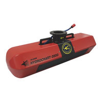
Klein Marine Systems, Inc. HYDROCHART 3500 Operation And Maintenance Manual (86 pages)
Brand:
Klein Marine Systems, Inc.
| Category:
Sonar
| Size: 33 MB
Table of Contents
Table of Contents
4
List of Figures
7
Sonar System Warranty
10
What Is Covered
10
Conditions of Warranty
11
Changes, Errors and Ommissions
12
Software License Agreement
13
Preface
15
What's in this Manual
15
Note, Warning and Caution Notices
16
Customer Service
16
CHAPTER 1: Overview
17
Applications
17
Key Features
17
455-Khz Operation
18
Sonar Head Unit
18
System Components
18
Topside Interconnect Unit (TIU)
18
Figure 1-1: the Hydrochart 3500 Sonar System Components
19
Deck Cable
20
CHAPTER 2 Specifications
22
Compass (Optional)
22
Motion Reference Sensor (Optional)
22
Sound Velocity Sensor (Optional)
22
Topside Interconnect Unit
23
Deck Cable
23
CHAPTER 3: Setup and Test
25
Locating the Topside Interconnect Unit
25
Unpacking and Inspection
25
Power Connection Requirements
26
Figure 3-2: Sonar Head Unit Mounting Flange and Bolt Circle
27
Installing the Sonar Head Unit
27
Figure 3-3: Arrow Label on the Sonar Head Unit Mounting Flange Should Point
28
Connecting the System Components
29
Installing the Motion Reference Unit
29
Installing the Sound Velocity Sensor
29
Figure 3-4: TIU Side Panels
31
Table 3-4: 120/240VAC Connector Pinouts
32
Table 3-3: NAV Connector Pinouts
32
Table 3-6: 1PPS Connector Pinouts
32
Table 3-2: LAN Connector Pinouts
32
Table 3-5: T/F Connector Pinouts
32
Table 3-7: 24VDC Connector Pinouts
32
Figure 3-5: the Sonar Interface Dialog Box-System Control Tab
34
3.10 Bathymetric System Calibration and Patch Test
35
3.10.1 Static Position Offsets
36
3.10.2 Latency Error
36
3.10.3 Roll Bias Test
36
3.10.4 Pitch Bias Test
36
3.10.5 Yaw Bias Test
37
Activating the System and Performing the Predeployment
33
Tests
33
Operator Controls and Indicators
33
CHAPTER 4: Maintenance
39
Daily Maintenance Checklist
39
Weekly and Long Term Maintenance Checklist
39
Disassembling and Reassembling the Sonar Head Unit
40
Disassembling the Sonar Head Unit
40
Figure 4-3: Sliding a Fairing off the Sonar Head Unit Frame
41
Figure 4-2: Removing the Phillips Head Screws from the Skid Plate
41
Figure 4-12: Sonar Head Unit Fully Assembled
47
Figure 4-13: Loosening the M6 Set Screw Securing the Sound Velocity Sensor
48
Figure 4-14: Removing the Sound Velocity Sensor and Its Adapter Sleeve
48
Figure 4-17: Sound Velocity Sensor, Sound Velocity Cable and Adapter Sleeve
50
Figure 4-18: Adapter Sleeve Positioned with Slot Visible through the Skid Plate
50
Installing the Sound Velocity Sensor
50
Installing the Compass
51
Removing and Installing the Optional Compass
51
Removing the Compass
51
Figure 4-4: Sonar Head Unit Frame with Fairings Removed
42
Figure 4-11: Sonar Electronics Housing Connector End Cap Connectors
46
Removing and Installing the Optional Sound Velocity
47
Sensor
47
Removing the Sound Velocity Sensor
47
Reassembling the Sonar Head Unit
45
Figure 4-20: Compass Mounted to Frame
51
CHAPTER 5: Technical Description
53
1Pps
53
DC Power
53
Ethernet 100Base-T
53
Topside Interconnect Unit
53
Figure 5-1: TIU Overall Block Diagram
54
Figure 5-2: TIU Electronics Chassis
55
Figure 5-3: Sonar Head Unit Overall Block Diagram
57
Transducer Arrays
59
Sonar Electronics
56
Sonar Head Unit
56
CHAPTER 6: System Troubleshooting
61
Deck Cable Troubleshooting
61
Topside Interconnect Unit Troubleshooting
61
Figure 6-1: Deck Cable Dry and Underwater Connector Pin Orientations, Face
62
Sonar Head Unit Troubleshooting
63
APPENDIX A: Sonar Uncertainty Model
65
A.1 IHO S-44 Uncertainty Definition
65
A.2 Generating the Uncertainty Estimates
65
Figure A-1: Klein Batch Processing GUI Dialog Box-Batch Processing Selections
66
Figure A-2: Klein Batch Processing GUI Dialog Box-XYZ File Selections
66
APPENDIX B Configuring and Updating the Sonar Head Unit
68
Querying or Changing the Sonar Head Unit IP Address
69
B.2 Editing the Sonar Head Unit Startup File
69
B.3 Updating the Sonar Head Unit Software
70
APPENDIX C Compass Calibration
74
C.2 Setting up for the Compass Calibration
74
C.3 Performing the Compass Calibration
74
Figure C-2: Setup Dialog Box
75
Figure C-3: Program Dialog Box
75
Figure C-4: Program Dialog Box-X and y Level Calibration Complete
76
Figure C-5: Compass Oriented at 90 Degrees
77
Figure C-6: Program Dialog Box-Z 90 Degree Calibration Complete
77
Figure C-7: Program Dialog Box-Soft Iron Calibration Selected
78
APPENDIX D: Collecting Data for Bathymetry Calibration
79
Sonar Head Unit Deployed One Meter below Survey Vessel's Hull
79
Figure
80
Data Collection Track and Water Depth
80
Table
81
List of Drawings
81
Advertisement
Advertisement
Related Products
Klein Marine Systems, Inc. HydroChart 5000
Klein Marine Systems, Inc. MA-X VIEW 600
Klein Marine Systems, Inc. Categories
Sonar
More Klein Marine Systems, Inc. Manuals
Login
Sign In
OR
Sign in with Facebook
Sign in with Google
Upload manual
Upload from disk
Upload from URL