
Related Manuals for Klein Marine Systems, Inc. HYDROCHART 3500


Summary of Contents for Klein Marine Systems, Inc. HYDROCHART 3500
- Page 1 3500 YDRO HART ONAR YSTEM Operations and Maintenance Manual P/N 11210087, Rev. 03 11 Klein Drive Salem, NH 03079-1249 U.S.A. Tel: (603) 893-6131 Fax: (603) 893-8807 www.KleinMarineSystems.com...
- Page 2 Corporation. ® Kevlar is a registered trademark of the DuPont Company. ® CARIS is a registered trademark of CARIS. ® HYPACK is a registered trademark of HYPACK, Inc. HydroChart 3500 Sonar System Operations and Maintenance Manual P/N 11210087, Rev. 03...
- Page 3 WARNING Klein Marine Systems recommends all troubleshooting be done by a trained technician. Some circuits in the HydroChart 3500 Sonar System have voltages as high as 1500 volts. Failure to observe these warnings could result in injuries to personnel. CAUTION...
-
Page 4: Table Of Contents
Deck Cable ......... 2-3 HydroChart 3500 Sonar System Operations and Maintenance Manual... - Page 5 CHAPTER 3: Setup and Test ....... 3-1 Unpacking and Inspection ......3-1 Locating the Topside Interconnect Unit .
- Page 6 APPENDIX E: Outline Drawings ......E-1 HydroChart 3500 Sonar System Operations and Maintenance Manual...
-
Page 7: List Of Figures
Figure 1-1: The HydroChart 3500 Sonar System Components ....1-3 LAN Cable, Navigation Cable Pigtail and AC and DC Power Cords ..3-2... - Page 8 Data Collection Track and Water Depth ......D-2 HydroChart 3500 Sonar System Operations and Maintenance Manual...
- Page 9 List of Tables Table 3-1: TIU Power Cord Wiring ......... . 3-2 LAN Connector Pinouts .
-
Page 10: Sonar System Warranty
Sonar System Warranty What Is Covered LIMITED WARRANTY Subject to the conditions set forth below, equipment sold by Seller is warranted against defects in materials and workmanship, and Seller will repair or exchange any parts proven to be malfunctioning under normal use for one year (12 months) from the date of Delivery as follows: a) SONAR and other associated manufactured products, with the following exceptions:... -
Page 11: Conditions Of Warranty
Repairs and replacements under warranty have the same warranty as the original product for the remaining balance of the warranty period for the original product existing prior to notice of the warranty claim. HydroChart 3500 Sonar System Operations and Maintenance Manual P/N 11210087, Rev. 03... -
Page 12: Changes, Errors And Ommissions
Any failure to meet the foregoing conditions of warranty will automatically void this limited warranty. This warranty gives Buyer specific legal rights, and Buyer may also have other rights, which vary from State to State, Province to Province or Country to Country. DISPUTES Seller and Buyer agree that all disputes in any way relating to, arising under, connected with, or incident to this agreement, and over which the federal courts have subject matter jurisdiction, shall be litigated, if at all, exclusively in the... -
Page 13: Software License Agreement
© (KMS) for end users of SonarPro software for the KMS Series 3000, UUV-3500, 3900, 4900, 5000, 5000 V2, 5900, HydroChart 3500, HydroChart 5000, and D3500TF Sonar Systems. YOU SHOULD CAREFULLY READ THE FOLLOWING TERMS AND CONDITIONS BEFORE USING THIS PRODUCT. IT CONTAINS SOFTWARE, THE USE OF WHICH IS LICENSED BY KMS, TO ITS CUSTOMERS FOR THEIR USE ONLY, AS SET FORTH BELOW. - Page 14 BATHYMETRIC PROCESSING ATTRIBUTION: Bathymetric processing derived from DGA/GESMA publication in IEEE OCEAN'S 05 Europe Conference Proceedings: "Bathymetric Sidescan Sonar: a System Dedicated to Rapid Environment assessment, ref: 10.1109/OCEANSE.2005.1511695. EXPORT RESTRICTIONS: You agree that you will not export or re-export the Software or accompanying documentation (or any copies thereof) or any products utilizing the Software or such documentation in violation of any applicable laws or regulations of the United States or the country in which you obtained them.
-
Page 15: Preface
Chapter 4: Maintenance. Provides instructions for maintaining the HydroChart 3500 Sonar System on a daily, a weekly and a long term basis. Chapter 5: Technical Description. Provides an overall description of the HydroChart 3500 Sonar System electronics to assist in troubleshooting, repair or adding optional equipment. -
Page 16: Note, Warning And Caution Notices
Appendix D: Bathy Systems Calibration Procedure. Provides a procedure on how to calibrate a bathy system to align the phase differences among the bathy channels after replacing one or more components in the bathy channel path. Appendix E: Outline Drawings. Provides outline drawings for reference purposes only. -
Page 17: Chapter 1: Overview
CHAPTER 1: O VERVIEW The HydroChart 3500 Sonar System is a lightweight, compact, one person deployable shallow water hydrographic survey system which makes use of Klein Marine Systems proprietary wideband "chirp" technology to simultaneously collect IHO (International Hydrographic Organization) quality bathymetry and co- registered, geo-referenced, high resolution side scan sonar data. -
Page 18: 455-Khz Operation
CHAPTER 1 Overview 455-kHz Operation The HydroChart 3500 Sonar System operates at 455 kHz which provides excellent detection of medium to large targets at ranges exceeding 175 meters per side for a total swath of 350 meters. Bathymetry coverage is up to 12 times the altitude, and all acquired data supports the IHO S-44 Special Order Standard for Hydrographic Surveys. -
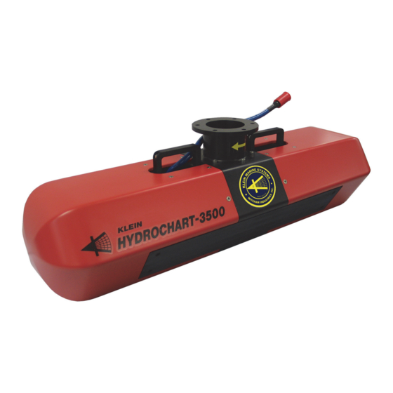
Page 19: Figure 1-1: The Hydrochart 3500 Sonar System Components
Carrying handle (2) Mounting flange Plastic fairing (1 forward, 1 aft) Transducer array (1 port, 1 starboard) Sonar Head Unit Deck cable underwater connector and locking collar Deck cable dry connector Deck cable Figure 1-1: The HydroChart 3500 Sonar System Components... -
Page 20: Deck Cable
TIU and an underwater connector with a locking collar at the other end for connecting to the jumper cable on the Sonar Head Unit. HydroChart 3500 Sonar System Operations and Maintenance Manual P/N 11210087, Rev. 03... - Page 21 PECIFICATIONS This chapter includes the physical and performance specifications for the HydroChart 3500 Sonar System Sonar Head Unit, TIU and deck cable. The Sonar Head Unit connects to the TIU using the deck cable. NOTE These specifications are subject to change without notice. Actual performance may also vary depending on the environmental and operating conditions.
-
Page 22: Chapter 2 Specifications
The optional sound velocity sensor is an AML Oceanographic Micro•X. Range: 1375–1625 m/s ±0.05 m/s Accuracy: Up to 25 Hz Sample rate: RS-232 at 9600 baud Serial interface: 8–26 VDC Power: HydroChart 3500 Sonar System Operations and Maintenance Manual P/N 11210087, Rev. 03... -
Page 23: Topside Interconnect Unit
Topside Interconnect Unit Topside Interconnect Unit 25.4 cm (10.0 in.) long Size: 20.3 cm (8.0 in.) wide 11.4 cm (4.5 in.) high 1.5 kg (3.2 lb) Weight: 120 or 240 VAC, 50–60 Hz; or 24 VDC Power: Ethernet 100Base-T Sonar Head Unit/PC interface: RS-232, NMEA 0183 Navigation input: 1PPS from a navigation device or... -
Page 25: Chapter 3: Setup And Test
CHAPTER 3: S ETUP AND The HydroChart 3500 Sonar System is designed to be easily set up and deployed. This chapter provides instructions on how to unpack the system components, set them up, and turn on and test the system. Descriptions of all the connectors and the power on/off control and indicator on the TIU are also included. -
Page 26: Power Connection Requirements
Figure 3-1: Power Connection Requirements The HydroChart 3500 Sonar System requires 120 or 240 VAC, 50–60 Hz power to operate. A 24 VDC power source can also be used to power the system. The system is designed to protect against over and under voltage and transient spikes. -
Page 27: Installing The Sonar Head Unit
Installing the Sonar Head Unit Installing the Sonar Head Unit When installing the Sonar Head Unit, lightly grease the pins of the jumper cable connector with silicone grease before connecting the deck cable to it. Silicone grease serves an important lubricating and corrosion protection function. Use a high quality, nonconducting grease such as Dow Corning DC-4. -
Page 28: Figure 3-3: Arrow Label On The Sonar Head Unit Mounting Flange Should Point
TIU power cable is disconnected from the power source. Failure to follow this practice may result in personal injury or damage to the Sonar Head Unit or to the TIU electronics, or to both. HydroChart 3500 Sonar System Operations and Maintenance Manual P/N 11210087, Rev. 03... -
Page 29: Installing The Motion Reference Unit
Secure the deck cable to the Sonar Head Unit using tie-wraps. Installing the Motion Reference Unit The HydroChart 3500 Sonar System optionally includes the Klein Marine Systems KMS-02 Motion Reference Sensor which is factory installed inside the electronics bottle. The system is also capable of interfacing with several other industry- standard motion reference systems. - Page 30 Connect the AC power cord to the 120/240VAC connector of the TIU and to a 120 or 240 VAC, 50–60Hz power source, or connect the DC power cord to the 24VDC connector and to a 24 VDC power source. HydroChart 3500 Sonar System Operations and Maintenance Manual P/N 11210087, Rev. 03...
-
Page 31: Figure 3-4: Tiu Side Panels
Connecting the System Components 24VDC connector 120/240VAC connector T/F connector 1PPS Power/transmit connector indicator connector D/C–OFF–A/C connector switch Figure 3-4: TIU Side Panels... -
Page 32: Table 3-2: Lan Connector Pinouts
T/F Connector Pinouts Table 3-2: Table 3-5: Connector Pinouts FUNCTION FUNCTION +30 VDC Return +30 VDC 1PPS LED Trigger NAV TxD NAV RxD Table 3-3: LAN Rx- Connector Pinouts LAN Rx+ FUNCTION LAN Tx- LAN Tx+ +30 VDC +30 VDC Return Table 3-6: 1PPS Connector Pinouts FUNCTION... -
Page 33: Operator Controls And Indicators
Activating the System and Performing the Predeployment Tests The HydroChart 3500 Sonar System should be activated and a few predeployment tests should be performed before starting an actual survey. Before activating the system, however, SonarPro should be installed on the PC. For instructions on how to install and run SonarPro, refer to the "SonarPro User Manual."... -
Page 34: Figure 3-5: The Sonar Interface Dialog Box-System Control Tab
Enable Low Freq. Transmit and then click Click the button on the Real-Time tool bar in the Sonar Viewer Play window. HydroChart 3500 Sonar System Operations and Maintenance Manual P/N 11210087, Rev. 03... -
Page 35: 3.10 Bathymetric System Calibration And Patch Test
3-11 Bathymetric System Calibration and Patch Test Verify that the Sonar Head Unit is transmitting by viewing the output pulse in the Scan window. Also check that navigation data are being displayed in the Information window. Perform a rub test on the port and starboard transducers to confirm that the receivers are operating properly. -
Page 36: 3.10.1 Static Position Offsets
10–20 degrees, for 200–300 meters. It may be possible to use a channel feature instead of a long sloping bottom. Speed for the test should be equal for both lines. HydroChart 3500 Sonar System Operations and Maintenance Manual P/N 11210087, Rev. 03... -
Page 37: 3.10.5 Yaw Bias Test
3-13 Bathymetric System Calibration and Patch Test 3.10.5 Yaw Bias Test For the yaw bias test the objective is to determine azimuth offset error between the motion reference unit and the sonar arrays. For this test it is recommended that the survey vessel run two pairs of adjacent lines on reciprocal headings over a flat bottom with a prominent bathymetric feature, such as the edge of a ship channel. -
Page 39: Chapter 4: Maintenance
CHAPTER 4: M AINTENANCE This chapter provides instructions for maintaining the HydroChart 3500 Sonar System on a daily, a weekly and a long term basis. In addition, instructions are provided for disassembling and reassembling the Sonar Head Unit. Daily Maintenance Checklist Perform the following maintenance steps at the end of each day’s operation:... -
Page 40: Disassembling And Reassembling The Sonar Head Unit
M6 x 16 mm Phillips head from the Top of the Forward and Aft Fairings screws that secure the top of the forward and aft fairings to the frame. HydroChart 3500 Sonar System Operations and Maintenance Manual P/N 11210087, Rev. 03... -
Page 41: Figure 4-2: Removing The Phillips Head Screws From The Skid Plate
Disassembling and Reassembling the Sonar Head Unit Turn the Sonar Head Unit on its side and remove the six M6 x 16 mm Phillips head screws that secure the bottom of the forward and aft fairings and the skid plate to the frame. Skid plate Removing the Phillips Head Screws Figure 4-2:... -
Page 42: Figure 4-4: Sonar Head Unit Frame With Fairings Removed
Jumper cable is installed. RX PORT transducer cable TX PORT transducer cable RX STBD transducer cable Cables Disconnected from Sonar Figure 4-5: Electronics Housing HydroChart 3500 Sonar System Operations and Maintenance Manual P/N 11210087, Rev. 03... - Page 43 Disassembling and Reassembling the Sonar Head Unit If it is required to remove the transducer arrays, use the 4-mm hex key to Socket head remove the four M5 x 20 cap screws (4) mm socket head cap screws and rubber washers that secure each of them to the frame.
- Page 44 O-ring surface inside the housing. Lay the sonar electronics on a clean, flat, dry surface. Figure 4-9: Pulling the Sonar Electronics Chassis out of the Sonar Electronics Housing HydroChart 3500 Sonar System Operations and Maintenance Manual P/N 11210087, Rev. 03...
-
Page 45: Reassembling The Sonar Head Unit
Disassembling and Reassembling the Sonar Head Unit 4.3.2 Reassembling the Sonar Head Unit To reassemble the Sonar Head Unit: 1. If the sonar electronics chassis was removed, verify that the O-ring on the connector end cap is clean and free of dirt or scratches. Also use a lint-free cloth or paper towel to clean the O-ring surface inside the housing and apply a light coat of silicone grease to this surface. -
Page 46: Figure 4-11: Sonar Electronics Housing Connector End Cap Connectors
Loosely attach the forward and aft fairings using all eighteen of the M6 x 16 mm Phillips head screws and then tighten the screws securely. The fully assembled Sonar Head Unit shown in Figure 4-12. HydroChart 3500 Sonar System Operations and Maintenance Manual P/N 11210087, Rev. 03... -
Page 47: Removing And Installing The Optional Sound Velocity
Removing and Installing the Optional Sound Velocity Sensor Sonar Head Unit Fully Assembled Figure 4-12: Removing and Installing the Optional Sound Velocity Sensor Should it be required to replace the optional sound velocity sensor, it can be accessed from under the sonar head after removing the forward fairing. The following tools are recommended: •... -
Page 48: Figure 4-13: Loosening The M6 Set Screw Securing The Sound Velocity Sensor
Sound velocity sensor Adapter Sleeve Removing the Sound Velocity Figure 4-14: Sensor and its Adapter Sleeve HydroChart 3500 Sonar System Operations and Maintenance Manual P/N 11210087, Rev. 03... - Page 49 4-11 Removing and Installing the Optional Sound Velocity Sensor Disconnect the sound velocity sensor cable from the S/V connector on the electronics housing connector end cap. S/V connector Disconnecting the Sound Velocity Figure 4-15: Sensor Cable from the S/V Connector on the Electronics Housing End Cap Remove the sound velocity sensor from its adapter...
-
Page 50: Installing The Sound Velocity Sensor
Figure 4-19. Adapter Sleeve Positioned with Figure 4-18: Slot Visible through the Skid Plate HydroChart 3500 Sonar System Operations and Maintenance Manual P/N 11210087, Rev. 03... -
Page 51: Removing And Installing The Optional Compass
4-13 Removing and Installing the Optional Compass Removing and Installing the Optional Compass Should it be required to replace or to recalibrate the optional compass, it can be accessed by removing the forward and aft fairings. The following tools are recommended: •... -
Page 53: Chapter 5: Technical Description
CHAPTER 5: T ECHNICAL ESCRIPTION This chapter provides an overview of the functional components and signal flows of the TIU and the Sonar Head Unit using block diagrams, wiring diagrams and descriptions of the connections and circuit board functions. This information can be useful for troubleshooting, making repairs and adding optional equipment. -
Page 54: Figure 5-1: Tiu Overall Block Diagram
ON/OFF 120/240 VAC 30 VDC switch 30 VDC Power Supply 24 VDC indicator Trigger Ethernet 100Base-T 1PPS 1PPS RS-232 Figure 5-1: TIU Overall Block Diagram... -
Page 55: Figure 5-2: Tiu Electronics Chassis
30 VDC Power Supply 120/240VAC connector DC–OFF–A/C switch Power/transmit connector indicator 1PPS connector 24VDC connector connector connector Figure 5-2: TIU Electronics Chassis... -
Page 56: Sonar Head Unit
CDI board. The Transmitter board is powered with 30 VDC from the CDI board. It also uses the 30 VDC to generate the high voltage required to drive the transducer arrays. HydroChart 3500 Sonar System Operations and Maintenance Manual P/N 11210087, Rev. 03... -
Page 57: Figure 5-3: Sonar Head Unit Overall Block Diagram
Port Transducer Array Transmitter board 30 VDC 1PPS Sound velocity sensor 8 channels 8 channels Receiver Receiver Trigger CDI board Transition board board RS-232 Compass Processor Ethernet board 100Base-T Stbd transducer array Figure 5-3: Sonar Head Unit Overall Block Diagram... - Page 58 Transmitter board Receiver board CDI board Processor board Receiver Transition (under mounting plate) board Location for optional MRU Figure 5-4: Sonar Head Unit Electronics Chassis...
-
Page 59: Transducer Arrays
Sonar Head Unit The Receiver board includes eight broad band, low power Receiver board. differential input receivers which input and amplify the sonar signals from preamplifiers in the transducer arrays. The amplified signals are output to a high speed 16-bit analog-to-digital converter (ADC), one for each receiver, and the digitized sonar data are processed, downsampled and output to the CDI board in accordance with command and control and clock signals from the CDI board. -
Page 61: Chapter 6: System Troubleshooting
ROUBLESHOOTING This chapter includes a few troubleshooting recommendations that should be followed if operational problems occur with the HydroChart 3500 Sonar System. Topside Interconnect Unit Troubleshooting If when turning on the TIU, the power/transmit indicator does not illuminate, or in about 45 seconds, begin flashing, turn off the TIU, and then do the following: Turn off the TIU and disconnect the AC or the DC power cable. -
Page 62: Figure 6-1: Deck Cable Dry And Underwater Connector Pin Orientations, Face
Turn on the TIU and check the power/transmit indicator. If it still does not operate properly, contact Klein Marine Systems, Inc. at (603) 893-6131 or your KMS sales representative. HydroChart 3500 Sonar System Operations and Maintenance Manual P/N 11210087, Rev. 03... -
Page 63: Sonar Head Unit Troubleshooting
Sonar Head Unit Troubleshooting Sonar Head Unit Troubleshooting If after performing both the TIU troubleshooting procedure and the deck cable troubleshooting procedure described above, the green indicator in the power switch still does not illuminate, or after about one minute, begin flashing, contact Klein Marine Systems, Inc. -
Page 65: Appendix A: Sonar Uncertainty Model
NCERTAINTY ODEL Data acquired by the HydroChart 3500 Sonar System can be post processed using the Klein Batch Processing GUI (graphical user’s interface) to compute both the sonar and bathymetry solutions and store the data in either Klein Marine Systems SDF format or in an industry standard format, such as XYZ or GSF. -
Page 66: Figure A-1: Klein Batch Processing Gui Dialog Box-Batch Processing Selections
APPENDIX A Sonar Uncertainty Model Klein Batch Processing GUI Dialog Box—Batch Processing Figure A-1: Selections Klein Batch Processing GUI Dialog Box—XYZ File Selections Figure A-2: HydroChart 3500 Sonar System Operations and Maintenance Manual P/N 11210087, Rev. 03... - Page 67 APPENDIX B: C ONFIGURING AND PDATING ONAR The Sonar Head Unit is configured at the factory. However, should changes be required, configuring and updating the Sonar Head Unit can be performed using Linux Updater. This program is automatically installed when installing SonarPro 12.1 and can be used to query or change the Sonar Head Unit IP address, edit the startup file of the Sonar Head Unit, or download and install software updates to the Sonar Head Unit.
-
Page 68: Appendix B Configuring And Updating The Sonar Head Unit
9. Enter the new address in the Enter New IP Address text box, and then click Set TPU IP Address A window opens confirming the change: 10. When starting SonarPro, use the new IP address. HydroChart 3500 Sonar System Operations and Maintenance Manual P/N 11210087, Rev. 03... -
Page 69: Querying Or Changing The Sonar Head Unit Ip Address
Editing the Sonar Head Unit Startup File B.2 Editing the Sonar Head Unit Startup File The startup file for the Sonar Head Unit is startupCdi3000.ini. To edit the startup file: Connect the system components as described in “Connecting the System Components”... -
Page 70: B.3 Updating The Sonar Head Unit Software
192.168.0.81. The address will already be displayed if it was queried or changed as described in “Querying or Changing the Sonar Head Unit IP Address” on page B-1. HydroChart 3500 Sonar System Operations and Maintenance Manual P/N 11210087, Rev. 03... - Page 71 Updating the Sonar Head Unit Software 6. Click Update TPU Software . An dialog box opens that enables file selection. 7. Select and open the update file to download and install. The file is downloaded to the Sonar Head Unit and installed, and the Sonar Head Unit software restarts.
- Page 73 APPENDIX C: C OMPASS ALIBRATION Although calibration of the OceanServer OS5000 Series Digital Compass is performed at the Klein Marine Systems, Inc. factory, it may be desirable to calibrate the compass to account for the differing magnetic fields in other parts of the world.
-
Page 74: Appendix C Compass Calibration
To perform the compass calibration: Turn on the laptop PC and start the OS5000 Windows Compass Demo Program. 2. Click Configure . The Setup dialog box opens as shown in Figure C-2. HydroChart 3500 Sonar System Operations and Maintenance Manual P/N 11210087, Rev. 03... -
Page 75: Figure C-2: Setup Dialog Box
Performing the Compass Calibration Setup Dialog Box Figure C-2: 3. Select the input port from the Input Port drop-down list box. 4. Select 19200 from the Baud Rate drop-down list box, and then click OK . 5. Click Program . The Program dialog box opens as shown in Figure C-3. -
Page 76: Figure C-4: Program Dialog Box-X And Y Level Calibration Complete
".." as shown in Figure C-6, and then press the Space bar to stop the calibration. 15. Disconnect the 5-pin bulkhead connector and remount the compass to the frame. 16. Reconnect the 5-pin bulkhead connector. HydroChart 3500 Sonar System Operations and Maintenance Manual P/N 11210087, Rev. 03... -
Page 77: Figure C-5: Compass Oriented At 90 Degrees
Performing the Compass Calibration Compass Oriented at 90 Degrees Figure C-5: Program Dialog Box—Z 90 Degree Calibration Complete Figure C-6:... -
Page 78: Figure C-7: Program Dialog Box-Soft Iron Calibration Selected
• Align the towfish west, and then press the Space bar. 19. Exit from the OS5000 Windows Compass Demo Program. Program Dialog Box—Soft Iron Calibration Selected Figure C-7: HydroChart 3500 Sonar System Operations and Maintenance Manual P/N 11210087, Rev. 03... -
Page 79: Appendix D: Collecting Data For Bathymetry Calibration
ATA FOR ATHYMETRY ALIBRATION The HydroChart 3500 Sonar System should be calibrated for its electronic and transducer channel phase mismatch so that the phase offsets can be compensated for in the bathymetry processing. The calibration processing is conducted by Klein Marine Systems using side scan data collected over a nearly flat sea floor. -
Page 80: Figure
APPENDIX D Collecting Data for Bathymetry Calibration Sonar Head Unit 2 m below surface 10 m Turning area 50 m Turning area 50 m 150 m Data Collection Track and Water Depth Figure D-2: HydroChart 3500 Sonar System Operations and Maintenance Manual P/N 11210087, Rev. 03... -
Page 81: Table
Listed in Table E-1 are the outline drawings included in this appendix. They are provided for reference purposes only. List of Drawings Table E-1: DRAWING TITLE Outline Drawing, Subsea Unit, Hydrochart 3500 14605417 Outline Drawing, Electronics Bottle, Hydrochart 3500 14605420 Outline Drawing, Transducers, Hydrochart 3500 14605418...
Need help?
Do you have a question about the HYDROCHART 3500 and is the answer not in the manual?
Questions and answers