Sign In
Upload
Manuals
Brands
Keysight Technologies Manuals
Measuring Instruments
N5244/5B
Keysight Technologies N5244/5B Manuals
Manuals and User Guides for Keysight Technologies N5244/5B. We have
1
Keysight Technologies N5244/5B manual available for free PDF download: Service Manual
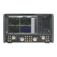
Keysight Technologies N5244/5B Service Manual (668 pages)
2-Port and 4-Port PNA-X Microwave Network Analyzers
Brand:
Keysight Technologies
| Category:
Measuring Instruments
| Size: 72.48 MB
Table of Contents
Table of Contents
5
Safety and Regulatory Information
13
Information in this Chapter
13
Chapter One At-A-Glance
13
Safety Symbols
14
General Safety Considerations
15
Safety Earth Ground
15
Before Applying Power
15
Servicing
17
Electrostatic Discharge Protection
19
Regulatory Information
21
Instrument Markings
21
Lithium Battery Disposal
24
General Product Information
25
Information in this Chapter
25
Chapter Two At-A-Glance
25
Maintenance
26
Physical Maintenance
26
Electrical Maintenance
26
Analyzer Options, Accessories, and Upgrades Available
27
Pulse I/O Adapter-N1966A
27
Required Service Test Equipment
28
Keysight Support, Services, and Assistance
31
Service and Support Options
31
Contacting Keysight
31
Shipping Your Analyzer to Keysight for Service or Repair
32
Tests and Adjustments
33
Information in this Chapter
33
Conventions Used for Hardkeys, Softkeys, and Menu Items
33
Chapter Three At-A-Glance
33
Before You Begin
36
Verify the Operating Environment
36
Protect against Electrostatic Discharge (ESD)
36
Allow the Analyzer to Warm up
37
Review the Principles of Connector Care
37
About System Verification and Performance Tests
39
System Specifications
39
Instrument Specifications
40
System Verification Procedure
40
Performance Tests
40
Certificate of Calibration
41
ANSI/NCSL Z540.3-2006 and ISO/IEC Verification
42
Non-Standards Compliant Verification
43
Preliminary Checks
44
The Operator's Check
44
The Test Port Cable Checks
47
System Verification
54
What the System Verification Verifies
54
Measurement Uncertainty
54
Measurement Traceability
55
Performing System Verification
56
Performance Tests
64
Source Power Accuracy Test
64
Source Maximum Power Output Test
65
Source Power Linearity Test
66
Frequency Accuracy Test
67
Trace Noise Test
68
Receiver Compression Test
69
Noise Floor Test
70
Calibration Coefficients Test
71
Dynamic Accuracy Test - Version 1
72
Dynamic Accuracy Test - Version 2
73
Receiver Noise Figure Test
75
Noise State Calibration Coefficients
76
Noise Jitter Test
76
Noise Receiver Linearity Test
77
Noise Receiver Compression Test
78
Dynamic Accuracy at Low Frequency (Available with Low Frequency Extension (LFE) Installed Option 205/220/420/425)
80
DC Continuity Test the LFE Board and Test Ports (Available with Low Frequency Extension (LFE) Installed Option 205/220/405/420/425)
82
Adjustments
83
Touchscreen Adjustment and Verification
83
10 Mhz Frequency Reference Adjustment
84
Synthesizer Bandwidth Adjustment
85
Source Adjustment
85
IF Gain Adjustment
86
Receiver Characterization
86
Receiver Adjustment
87
EE Default Adjustment
89
IF Response Adjustment (Available Only with Option S93093/4A/B and or S93900/1/2/4/5/7A/B Installed)
89
Noise Figure Adjustment (Available with Option 029 with S93029A/B Installed)
90
LFE Receiver Adjustment (Available with Low Frequency Extension (LFE) Installed Option 205/220/420/425)
93
Troubleshooting
95
Information in this Chapter
95
Chapter Four At-A-Glance
96
Conventions Used for Hardkeys, Softkeys, and Menu Items
97
Operating the Analyzer with Covers Removed
98
Protect against Electrostatic Discharge (ESD)
99
Assembly Replacement Sequence
100
Getting Started with Troubleshooting
101
Check the Basics
101
Troubleshooting Organization
102
Power up Troubleshooting
103
Power Supply Check
104
Troubleshooting LCD Display Problems
109
Front Panel Troubleshooting
111
Front Panel Keypad and RPG Test
111
A3 Display Test
114
Checking the A2 USB Board
115
A1 Front Panel Interface Board
116
Rear Panel Troubleshooting
118
Checking the USB Ports
118
Checking the CONTROLLER Port
118
LAN Troubleshooting
119
Measurement System Troubleshooting
125
Before You Begin-Consider: Where Do You See a Problem
125
Verifying the A, B, C, D, and R Traces (Standard S-Parameter Mode)
127
Where to Begin Troubleshooting
128
Checking the Source Group
131
Checking the Signal Separation Group
142
Checking the Receiver Group
146
Instrument Simplified Block Diagrams - LFE
150
2-Port N5290A System Block Diagram (201 and 205)
150
2-Port N5290A System Block Diagram (202 and 205)
151
4-Port N5290A System Block Diagram (401)
152
Instrument Block Diagrams - 2-Port (Sheet 1), Non-LFE and Non-DDS
156
Synthesizers)
156
Instrument Block Diagrams - 2-Port (Sheet 2), Non-LFE and DDS
158
Assemblies)
158
Microwave PNA-X, N5244/5B - 2-Port, Non-LFE and DDS
158
Instrument Block Diagrams - 4-Port (Sheet 3), Non-LFE and Non-DDS (Version 6
160
Synthesizers)
160
Microwave PNA-X, N5244/5B - 4-Port, LFE and Non-DDS (Version 6 Synthesizers)
162
Instrument Block Diagrams - 4-Port (Sheet 5), Non-LFE and DDS
164
Assemblies)
164
Microwave PNA-X, N5244/5B - 4-Port, Non-LFE and DDS
164
Assemblies)
166
Instrument Block Diagrams - 4-Port (Sheet 6), LFE and DDS
166
Assemblies)
168
Theory of Operations
169
Information in this Chapter
169
Chapter Five At-A-Glance
169
Network Analyzer System Operation
171
Functional Groups of the Network Analyzer
174
Synthesized Source Group Operation
178
Basic Operation
179
A4, A15, and A17 13.5 Ghz Synthesizer Boards (S/N Prefixes <6021 Only)
191
A5 and A10 26.5 Ghz Source Boards
193
A7, A8, A12, and A13 50 Ghz Doubler Boards
193
A25 Multiplier/Amplifier 26.5 Board (HMA26.5)
194
A14 Frequency Reference Board (S/N Prefixes <6021 Only)
194
A23 Test Set Motherboard
195
A70 4-Port and A75 2-Port Low Frequency Extension (LFE) Board
198
Signal Separation Group Operation
212
Configurable Test Set
212
A29-A32 Reference Couplers
213
A33-A36 Test Port Couplers
213
A38-A41 60-Db Source Step Attenuators and A42-A45 Bias Tees (Optional)
217
A50-A53 Mechanical Switches and A54 Combiner (Optional)
217
Receiver Group Operation
219
A46-A49 35-Db Receiver Step Attenuators (Optional)
219
A37 Reference Mixer Switch
219
A27 and A28 Mixer Bricks
219
A24 if Multiplexer Board
220
A16 SPAM Board (Analog Description)
221
Digital Processing and Digital Control Group Operation
225
Front Panel Subgroup
227
Data Acquisition and Processing Subgroup
228
Power Supply Group Operation
230
Noise Measurement Group Operation (Option S93029A)
230
A56 Test Port 1 Option 029 Switch
231
A64 Test Port 1 Option 029 Tuner
231
A57 Test Port 2 Option 029 Switch
231
A59 Noise Receiver (Downconverter)
231
A9 Noise Receiver Board
231
Replaceable Parts
235
Information in this Chapter
236
Chapter Six At-A-Glance
236
Ordering Information
237
Assembly Replacement Sequence
238
Rebuilt-Exchange Assemblies
239
Replaceable Parts Listings
241
Front Panel Assembly, Front Side, All Options
247
Front Panel Assembly, Back Side, All Options
249
Top Assemblies and Cables, All Options, Serial Number Prefixes <6021
253
Top Assemblies and Cables, All Options, Serial Number Prefixes ≥6021
261
2-Port Configurations, Serial Number Prefixes <6021
309
2-Port Configurations, Serial Number Prefix ≥6021
315
4-Port Configuration, Serial Number Prefix <6021
363
4-Port Configurations, Serial Number Prefix ≥6021
442
Rear Panel Assembly, All Options
523
Fan Assemblies, All Options
525
Advertisement
Advertisement
Related Products
Keysight Technologies N5244A
Keysight Technologies N5244B
Keysight Technologies N5244AU- 942
Keysight Technologies N5244BU-679
Keysight Technologies N5245A
Keysight Technologies PNA-X N5241A
Keysight Technologies N5249AU-922
Keysight Technologies N5242-60122
Keysight Technologies N5249BU-617
Keysight Technologies N5245AU- 942
Keysight Technologies Categories
Measuring Instruments
Test Equipment
Control Unit
Portable Generator
Power Supply
More Keysight Technologies Manuals
Login
Sign In
OR
Sign in with Facebook
Sign in with Google
Upload manual
Upload from disk
Upload from URL