Sign In
Upload
Manuals
Brands
KeepRite Manuals
Air Conditioner
DLFDAB
KeepRite DLFDAB Manuals
Manuals and User Guides for KeepRite DLFDAB. We have
2
KeepRite DLFDAB manuals available for free PDF download: Service Manual, Installation Instruction
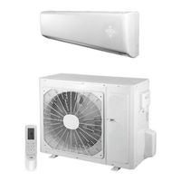
KeepRite DLFDAB Service Manual (83 pages)
High Wall Ductless Split System - Sizes 09 to 36
Brand:
KeepRite
| Category:
Air Conditioner
| Size: 25 MB
Table of Contents
Table of Contents
1
Introduction
1
Page Safety Considerations
1
Indoor Unit
2
Outdoor Unit
2
Model / Serial Number Nomenclatures
2
Dimensions − Indoor
3
Indoor Unit Dimensions
3
Indoor Mounting Plate
3
Dimensions − Outdoor
4
Outdoor Clearances
5
Clearances − Outdoor
5
Outdoor Unit Clearance
5
Clearances − Indoor
5
Communication Wiring
6
Dlfcab / Dlccar / Dlfchb / Dlcchr
6
Dlfdab / Dlcdar / Dlfdhb / Dlcdhr
6
Wiring
6
Connection Diagram 9K & 12K Units 115V
7
Connection Diagram 9K & 12K Units 208/230V
7
Connection Diagrams
7
Wiring Diagram − Indoor Unit − Dlfcab / Dlfchb
8
Indoor Unit Sizes 18 − 24 (208/230V)
9
Indoor Unit Sizes 30 − 36 (208/230V)
9
Wiring Diagram − Outdoor Unit − Dlccar / Dlcchr
10
Outdoor Unit Size 18 (208/230V)
11
Outdoor Unit Size 24 (208/230V)
11
Wiring Diagram − Indoor Unit − Dlfdab / Dlfdhb
12
Outdoor Unit Sizes 30 − 36 (208/230V)
12
Indoor Unit Sizes 09 − 12 (115V)
12
Indoor Unit Sizes 09 − 24 (208/230V)
13
Outdoor Unit DLCDAR Sizes 09 − 12 (208−230V)
14
Wiring Diagram − Outdoor Unit − Dlcd
14
Outdoor Unit DLCDAR Sizes 09 − 12 (115V)
14
Outdoor Unit DLCDAR Sizes 18−24 (208−230V)
15
Outdoor Unit DLCDHR Sizes 9−12 (115 V)
15
Outdoor Unit DLCDHR Sizes 09−12 (208/230V)
16
Outdoor Unit DLCDHR Size 18−24 (208/230V)
16
Outdoor Unit DLCDHR Size 30 (208/230V)
17
Outdoor Unit DLCDHR Size 36 (208/230V)
17
Pcb Printed Diagrams
18
Indoor Units DLFCAB / DLFCHB Sizes 9 to 24 Bottom View
19
—Indoor Units DLFCAB / DLFCHB
19
Indoor Units DLFCAB / DLFCHB Sizes 9 to 24 Top View
19
Indoor Units DLFCAB / DLFCHB Sizes 30 and 36 Top View
20
Indoor Units DLFCAB / DLFCHB
20
Indoor Units DLFCAB / DLFCHB Sizes 30 and 36 Bottom View
20
Outdoor Units DLCCAR / DLCCHR 115V Sizes 9 and 12 Top View
21
Outdoor Units DLCCAR / DLCCHR
21
Outdoor Units DLCCAR / DLCCHR 208/230V Sizes 9 and 12 Top View
22
Outdoor Units DLCCAR / DLCCHR 208/230V Sizes 9 and 12 Bottom View
22
Outdoor Units DLCCAR / DLCCHR Size 18 Bottom View
23
Outdoor Units DLCCAR / DLCCHR Size 18 Top View
23
Outdoor Units DLCCAR / DLCCHR Size 24 Top View
24
Outdoor Units DLCCAR / DLCCHR Sizes 30 and 36 Top View
25
Outdoor Units DLCCAR / DLCCHR Sizes 30 and 36 Bottom View
25
Indoor Units DLFDAB / DLFDHB Sizes 9 − 24 Top View
26
Indoor Units DLFDAB / DLFDHB Sizes 9 − 24 Bottom View
26
Indoor Units DLFDHB Sizes 30 and 36 Top View
27
Indoor Units / DLFDHB Sizes 30 and 36 Bottom View
27
Outdoor Units DLCDAR / DLCDHR Sizes 9 and 12 Top View
28
Outdoor Units DLCDAR / DLCDHR Sizes 9 and 12 Bottom View
28
Outdoor Units DLCDAR / DLCDHR Sizes 18 and 24 Bottom View
29
Outdoor Units DLCDAR / DLCDHR Sizes 18 and 24 Top View
29
Outdoor Units DLCDHR Sizes 30 and 36 Top View
30
Outdoor Units DLCDHR Sizes 30 and 36 Bottom View
30
Refrigeration System Diagrams
31
Refrigeration Diagrams
31
Refrigerant Lines
32
General Refrigerant Line Sizing
32
Piping Information DLFCAB / DLCCAR / DLFCHB / DLCCHR
32
Triple Evacuation Method
33
Using Vacuum Pump
33
Deep Vacuum Method
33
System Evacuation and Charging
33
Brief Description of Modes and Functions
34
Drying Mode
34
Cooling Mode
34
Sequence of Operation
34
Leakage Detection
35
I Feel Control Mode
35
Ambient Temperature Display Control Mode
35
Off−Peak Energization Function
35
Required Tools
36
Troubleshooting
36
Flashing LED of Indoor/Outdoor Unit and Primary Judgment
37
Malfunction of Temperature Sensor F1, F2
41
Indoor Unit
41
Troubleshooting for the Main Function
41
Malfunction of Blocked Protection of IDU Fan Motor H6
42
Malfunction of Protection of Jumper Cap C5
43
Malfunction of over Current Protection E5
44
Communication Malfunction E6
45
Outdoor Unit
46
High Temperature and Overload Protection (E8)
49
Start−Up Failure (LC)
50
Overload and High Discharge Temperature Malfunction
51
ODU Fan Motor Can Not Operate
52
Compressor Does Not Operate
52
Air Conditioner Is Leaking
52
Abnormal Sound and Vibration
52
Communication Malfunction (E6)
53
Malfunction Diagnosis Process
53
Horizontal Louver Can Not Swing
54
Poor Cooling (Heating) for Air Conditioner
54
Air Conditioner Can Not Start up
54
—ODU Fan Motor Does Not Operate
55
—Compressor Can Not Operate
55
—Air Conditioner Is Leaking
55
—Abnormal Sound and Vibration
55
Disassembly Instructions Indoor Unit
56
Remove Electric Box
58
Remove Evaporator
58
Remove Swing Blade
60
Remove Cross Flow Blade and Motor
61
Remove the Panel
62
Remove the Top Cover
62
Remove the Front Grille
62
Disassembly Instructions Outdoor Unit
62
Remove the Front Panel
63
Remove the Right Side Plate
63
Remove the Axial Flow Blade
63
Remove the Motor and Motor Support
64
Remove the Electric Box Assy
64
Remove the Clapboard Sub-Assy
64
Remove the 4-Way Valve Assy
65
Remove the Compressor
65
Remove Handle
66
Remove Top Panel
66
Remove Front Side Panel
66
Remove Grille and Panel
67
Remove Right Side Plate
67
Remove Axial Flow Blade
67
Remove Motor
68
Remove 4-Way Valve
69
Remove Isolation Sheet
69
Remove Motor Support
69
Remove Gas Valve and Liquid Valve
70
Remove Valve Support
70
Remove Compressor
70
Remove Left Side Plate
71
Remove Chassis and Condenser
71
Remove the Big Handle,Valve Cover and the Top Cover
72
Remove the Top Panel
72
Remove the Front Side Panel
72
Remove the Grille and Panel
73
Remove the Electric Box
74
Remove the Motor
74
Remove the Motor Support
75
Remove the Isolation Sheet
75
Remove the 4-Way Valve
75
Remove the Gas Valve and Liquid Valve
76
Remove the Valve Support
76
Remove the Left Side Plate
77
Remove the Chassis and Condenser
77
Connection Pipe Configuration
78
—Set Temperature
78
—Ambient Temperature
78
Fahrenheit and Celsius Reference Sheet
78
Appendix
78
Pipe Expanding Method
79
Put on the Union Nut
79
Cut the Pipe
79
Expand the Port
79
List of Resistance for the Temperature Sensor
80
Resistance Table of Tube Temperature Sensors for Indoor and Outdoor
81
Advertisement
KeepRite DLFDAB Installation Instruction (16 pages)
High- Wall Ductless Split System Sizes 09 - 36
Brand:
KeepRite
| Category:
Air Conditioner
| Size: 1 MB
Table of Contents
Table of Contents
1
Safety Considerations
2
General
2
System Requirements
2
Piping
2
Dimensions- Indoor
6
Dimensions- Outdoor
7
Clearances- Indoor
8
Clearances- Outdoor
8
Installation Guide
9
Indoor Unit Installation
9
Install Mounting Plate
9
Drill Hole in Wall for Interconnecting Piping, Drain and Wiring
9
Outdoor Unit Installation
9
Piping Connections to Outdoor Unit
9
Sizes
9
Install All Power, Interconnecting Wiring and Piping to Indoor Unit
11
System Vacuum and Charge
11
Start- up
13
Wiring Diagrams
14
Troubleshooting
15
Advertisement
Related Products
KeepRite DLFCAB
KeepRite DLFCHB
KeepRite DLFDHB
KeepRite DLCCHR
KeepRite DLCDAR
KeepRite DLCCAR
KeepRite DLCDHR
KeepRite DLCPRA Series
KeepRite DLCPRAH12AAK
KeepRite DLCPRAH18AAK
KeepRite Categories
Air Conditioner
Furnace
Air Compressor
Heat Pump
More KeepRite Manuals
Login
Sign In
OR
Sign in with Facebook
Sign in with Google
Upload manual
Upload from disk
Upload from URL