Sign In
Upload
Manuals
Brands
Kaliburn Manuals
Welding System
ProLine 2200
Kaliburn ProLine 2200 Manuals
Manuals and User Guides for Kaliburn ProLine 2200. We have
1
Kaliburn ProLine 2200 manual available for free PDF download: User Manual
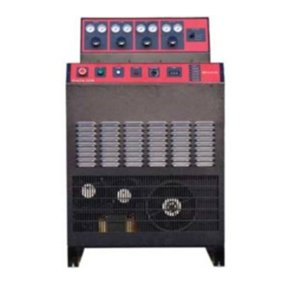
Kaliburn ProLine 2200 User Manual (138 pages)
Precision Plasma Cutting System
Brand:
Kaliburn
| Category:
Welding System
| Size: 6 MB
Table of Contents
Revision History
2
Limited Warranty
4
Table of Contents
5
Section 1 Safety
9
General Precautions
9
Ultraviolet Radiation Protection
9
Noise Protection
9
Toxic Fume Prevention
9
Electric Shock Prevention
10
Fire Prevention
11
Explosion Prevention
11
Health Support Equipment
12
Safety Standards Booklet Index
12
Section 2 Specifications System Description
15
System Components
16
Power Supply Specifications
16
Figure 2-1 Power Supply Dimensions
17
Gas Console Specifications
18
Illustrations
19
Remote High Frequency Console Specifications
19
Figure 2-2 Remote High Frequency Console Mounting Dimensions
19
Torch Specifications
20
Figure 2-3 Torch Dimensions
20
Remote On/Off Control Specifications (Optional)
21
Figure 2-4 Remote On/Off Control Dimensions (Optional)
21
Hydrogen Manifold Specifications (Optional)
22
Figure 2-5 Hydrogen Manifold Dimensions (Optional)
22
Airborne Noise Emissions
23
Section 3 Installation Initial Inspection
25
System Interconnection
25
Figure 3-1 System Interconnection Diagram
26
Power Supply Installation
27
Remote High Frequency Installation
27
Torch Installation
27
Primary Power Connection
27
Figure 3-2 Primary Power Connections
28
Power Supply Output Connections
29
RHF Console Ground Connection
30
Figure 3-3 Power Supply Output Connections
31
Torch Leads to RHF Console Connections
32
Figure 3-4 Torch Leads to RHF Console Connections
33
Torch Connections
34
Figure 3-5 Torch Connections
36
Torch Head Connection
37
Gas Console Input Connections
38
Figure 3-6 Gas Console Input Connections
38
Gas Console Output Connections
39
Figure 3-7 Gas Console Output Connections
39
CNC Machine Interface Connections
40
Torch Coolant Requirements
41
Initial Filling of the Torch Coolant Reservoir
42
Optional Remote On/Off Control Installation
43
Optional Hydrogen Manifold Installation
43
Section 4 Operation
45
Power Supply Front Panel Controls
45
Figure 4-1 Front Panel Controls
45
Optional Hydrogen Manifold Controls
47
Figure 4-2 Hydrogen Manifold Controls (Optional)
47
Setting up a Cut
48
Gas Purge
49
Making a Cut
50
Consumable Life
50
Cut Quality
51
Section 5 Maintenance and Troubleshooting
81
Routine Maintenance
81
Replacing the Torch Coolant
83
230/460V 60 Hz Transformer Configurations
84
Figure 5-1 230V 60 Hz Transformer Configuration
84
Figure 5-2 460V 60 Hz Transformer Configuration
85
Microprocessor Status Led's
86
Microprocessor Sequence of Operation
87
Troubleshooting Using the Control Panel Status Led's
88
Troubleshooting Using the Microprocessor Error LED
89
General Troubleshooting
90
Chopper Test Procedure
92
Figure 5-3 Chopper Diagnostics - Part 1
94
Figure 5-4 Chopper Diagnostics - Part 2
95
Section 6 Parts List
97
Power Supply
97
Figure 6-1 Power Supply Front View
99
Figure 6-2 Power Supply Rear View
100
Figure 6-3 Power Supply Left Side View
101
Figure 6-4 Power Supply Right Side View
102
Remote High Frequency Console
103
Figure 6-5 Remote High Frequency Console
104
Torch and Torch Valve Assembly
105
Figure 6-6 Torch and Torch Valve Assembly
105
Shielded Torch Leads
106
Figure 6-7 Shielded Torch Leads
106
Gas Hose Package
107
Figure 6-8 Gas Hose Package
107
Coolant and Power Leads
108
Figure 6-9 Coolant and Power Leads
108
Work Ground Cable
109
Figure 6-10 Work Ground Cable
109
Torch Consumables - Mild Steel Cutting Copper Electrode
110
Figure 6-11 Torch Consumables - Mild Steel Cutting, Copper Electrode
110
Torch Consumables - Mild Steel Cutting Silver Electrode
111
Figure 6-12 Torch Consumables - Mild Steel Cutting, Silver Electrode
111
Torch Consumables - Stainless Steel Cutting (Air), Copper Electrode
112
Torch Consumables - Stainless Steel Cutting (Air), Silver Electrode
113
Torch Consumables - Stainless Steel Cutting (H17), Copper Electrode
114
Torch Consumables - Aluminum Cutting Copper Electrode
115
Figure 6-16 Torch Consumables - Aluminum Cutting, Copper Electrode
115
Torch Consumables - Aluminum Cutting Silver Electrode
116
Figure 6-17 Torch Consumables - Aluminum Cutting, Silver Electrode
116
Torch Consumables - Marking Copper Electrode
117
Figure 6-18 Torch Consumables - Marking, Copper Electrode
117
Gas Console Without Integrated Inova
118
Gas Console with Integrated Inova
119
Figure 6-19 Gas Console - Exterior
120
Figure 6-20 Gas Console - Interior
121
Power Supply Microprocessor P.C. Board
122
Figure 6-21 Power Supply Microprocessor P.C. Board
122
A.C. Detect P.C. Board
123
Figure 6-22 A.C. Detect P.C. Board
123
Power Supply Relay P.C. Board
124
Figure 6-23 Power Supply Relay P.C. Board
124
Power Supply I/O P.C. Board
125
Figure 6-24 Power Supply I/O P.C. Board
125
Gas Console Relay P.C. Board
126
Figure 6-25 Gas Console Relay P.C. Board
126
Remote On/Off Control Assembly (Optional)
127
Figure 6-26 Remote On/Off Control Assembly (Optional)
127
Remote On/Off Control Cable (Optional)
128
Figure 6-27 Remote On/Off Control Cable (Optional)
128
Hydrogen Manifold Assembly (Optional)
129
Figure 6-28 Hydrogen Manifold Assembly (Optional)
129
Hydrogen Manifold Interface Cable (Optional)
130
Figure 6-29 Hydrogen Manifold Interface Cable (Optional)
130
Consumable Spare Parts Kit
131
Appendix A Electromagnetic Compatibility (EMC)
135
Background
135
Installation and Use
135
Assessment of Area
136
Methods of Reducing Emissions
136
Advertisement
Advertisement
Related Products
Kaliburn FineLine 200PC
Kaliburn Spirit150a
Kaliburn Spirit200a
Kaliburn SR-100i
Kaliburn SR-45i
Kaliburn Categories
Welding System
More Kaliburn Manuals
Login
Sign In
OR
Sign in with Facebook
Sign in with Google
Upload manual
Upload from disk
Upload from URL