Sign In
Upload
Manuals
Brands
JVC Manuals
Camcorder
GR-DVL510U
JVC GR-DVL510U Manuals
Manuals and User Guides for JVC GR-DVL510U. We have
2
JVC GR-DVL510U manuals available for free PDF download: Service Manual, Instructions Manual
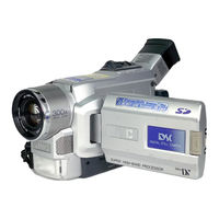
JVC GR-DVL510U Instructions Manual (92 pages)
JVC Digital Video Camera Instructions
Brand:
JVC
| Category:
Camcorder
| Size: 2 MB
Table of Contents
7 Getting Started Getting Started
7
Digital Video Camera
1
Safety Precautions
2
Some Do's and Don'ts on the Safe Use of Equipment
3
Provided Accessories
5
Automatic Demonstration
6
How to Attach the Core Filter
6
Table of Contents
7
Getting Started
7
Power
8
Charging the Battery Pack
8
Using the Battery Pack
9
Using Ac Power
9
Grip Adjustment
10
Viewfinder Adjustment
10
Shoulder Strap Attachment
10
Tripod Mounting
10
Date/Time Settings
11
Loading/Unloading a Cassette
12
Recording Mode Setting
13
Getting Started
14
Loading a Memory Card (GR-DVL557/DVL555/DVL357/DVL355 Only)
14
Picture Quality Mode Setting (GR-DVL557/DVL555/DVL357/DVL355 Only)
14
15 Video Recording & Playback Video Recording & Playback
15
Video Recording & Playback
15
Video Recording
16
Basic Recording
16
Journalistic Shooting
17
Self-Recording
17
Operation Mode
17
Zooming
18
Operation
18
Video Light
19
Time Code
20
Video Playback
21
Normal Playback
21
Still Playback
21
Shuttle Search
21
Frame-By-Frame Playback
21
Connections
22
Blank Search
24
Digital Still Camera (D.s.C.) Recording & Playback
25
D.s.C. Recording
26
Basic Shooting (Snapshot)
26
Snapshot Recording
26
D.s.C. Playback
28
Normal Playback
28
Auto Playback
28
INDEX Screen
29
Index Playback
29
Jump Playback
30
Protecting Images
31
Deleting Images
32
Setting Print Information (DPOF Setting)
34
To Print All Still Images (One Print for Each)
34
Initialising a Memory Card
36
37 Advanced Features Advanced Features
37
Features
37
For Recording
38
Night-Scope
38
Programme AE with Special Effects
38
Fade/Wipe Effects
40
Snapshot (for Video Recording)
42
Auto Focus/Manual Focus
43
Exposure Control
44
Iris Lock
44
White Balance Adjustment
45
Manual White Balance Operation
45
Using the Menu for Detailed Adjustment
46
For Recording Menu
46
Snap Mode
47
Continued on Next Page
47
For Playback Menu
50
Playback Sound
51
Sound Mode
51
Dubbing
52
Dubbing to a VCR
52
Dubbing from a VCR (GR-DVL557 Only)
53
Dubbing to or from a Video Unit with a DV Connector
54
Dubbing Images Stored in a Memory Card to a Tape (GR-DVL557/DVL555/DVL357/DVL355 Only)
55
Dubbing Images Recorded on a Tape to a Memory Card (GR-DVL557/DVL555/DVL357/DVL355 Only)
56
Using the Remote Control Unit
57
Installing the Batteries
57
Playback Special Effects
59
Slow-Motion Playback
59
Operation
59
Frame-By-Frame Playback
59
Playback Zoom
60
Set Remote/Vcr Code
61
Vcr Code List
61
Random Assemble Editing
61
Make Connections
62
Automatic Editing to Vcr
64
For more Accurate Editing
65
Audio Dubbing
66
Insert Editing (GR-DVL557/DVL555/DVL357/DVL355 Only)
67
System Connections
68
Connection to a Personal Computer
68
Connection to a Video Unit Equipped with a DV Connector
69
70 References References
70
References
70
Details
71
Troubleshooting
72
Troubleshooting
76
User Maintenance
77
After Use
77
Cleaning the Camcorder
77
Index
78
Controls, Connectors and Indicators
78
Other Parts
79
Indications
80
Blank Search
82
Warning Indications
83
Index
84
Cautions
85
Memory Cards
86
Lcd Monitor
86
Main Unit
86
Terms
88
Specifications
90
Specifications
91
Advertisement
JVC GR-DVL510U Service Manual (103 pages)
Brand:
JVC
| Category:
Camcorder
| Size: 19 MB
Table of Contents
Table of Contents
2
Important Safety Precautions
3
Section 1 Disassembly
5
Before Assembly and Disassembly
5
Precautions
5
Assembly and Disassembly
5
Destination of Connectors
5
Disconnection of Connectors (Wires)
5
Jigs and Tools Required for Disassembly, Assembly and Adjustment
6
Tools Required for Adjustments
6
Disassembly/Assembly of Cabinet Parts and Board Assembly
6
Disassembly Flow Chart
6
Disassembly Method
7
Monitor Assembly
12
Disassembly/Assembly of Monitor Assembly (for 2.5"-Type LCD)
12
Disassembly/Assembly of Hinge Assembly (for 2.5"-Type LCD)
12
Disassembly/Assembly of Monitor Assembly (for 3"/3.5"-Type LCD)
13
Disassembly/Assembly of Hinge Assembly (for 3"/3.5"-Type LCD)
13
E. Vf Assembly
14
Disassembly/Assembly of E. VF Assembly (for B/W VF)
14
Disassembly/Assembly of E. VF Assembly (for Color VF)
15
Disassembly/Assembly of Op Block Assembly/CCD Board Assembly
16
Precautions
16
How to Remove CCD Board Assembly and CCD Base Assembly
16
How to Assemble CCD Base Assembly and CCD Board Assembly
16
Replacement of Service Repair Parts
16
Emergency Display
17
Service Note
18
Section 2 Mechanism Adjustment
19
Preliminary Remarks on Adjustment and Repair
19
Precautions
19
Notes on Procedure for Disassemby/Assembly
19
Jigs and Tools Required for Disassembly, Assembly and Adjustment
20
Tools Required for Adjustments
20
Disassembly/Assembly of Mechanism Assembly
21
General Statement
21
Explanation of Mechanism Mode
21
Mechanism Timing Chart
22
Disassembly/Assembly of Mechanism Assembly
23
Follow Chart
23
Disassembly/Assembly
26
List of Procedures for Disassembly
32
Checkup and Adjustment of Mechanism Phase
33
Mechanism Adjustments
34
Assembling Slide Deck Assembly and Main Deck Assembly
34
Locating Tension Pole
35
Service Note
36
Jig Connector Cable Connection
38
Section 3 Electrical Adjustment
39
Precaution
39
Setup
40
Section 4 Charts and Diagrams
41
Notes of Schematic Diagram
41
Circuit Board Notes
42
Board Interconnections
43
Syscon Schematic Diagram
44
Pc if Schematic Diagram
45
Vtr Cpu Schematic Diagram
46
Mda Schematic Diagram
47
Audio Schematic Diagram
48
DV Main Schematic Diagram
49
Pre/Rec Schematic Diagram
50
Out Schematic Diagram
51
Ana in Schematic Diagram [Gr-Dvl915U]
52
Cam Dsp Schematic Diagram
53
Op Drive Schematic Diagram
54
Tg/Vdrv Schematic Diagram
55
Reg Schematic Diagram
56
Dsc/Usb Schematic Diagram
57
Monitor Schematic Diagram
58
Lcd Bl Schematic Diagram
59
CCD Schematic Diagram
60
Junction Schematic Diagram
60
Jack Schematic Diagram
61
B/W Vf Schematic Diagram
62
Main Circuit Board
64
Monitor Circuit Board
68
Lcd Bl Circuit Board
69
CCD and Junction Circuit Boards
70
Jack Circuit Board
71
Power System Block Diagram
72
Regulator System Block Diagram
73
Video System Block Diagram
74
Audio System Block Diagram
76
Voltage Charts
77
Parts List
83
Packing and Accessory Assembly <M1
83
Final Assembly <M2
85
Optical Block Section
85
Mechanism Assembly
86
Mechanism Assembly <M3
87
Electronic Viewfinder Assembly <M4> [Gr-Dvl815U/915U]
88
Electronic Viewfinder Assembly <M4> [Gr-Dvl510U/817U]
89
Monitor Assembly <M5> [Gr-Dvl510U]
90
Monitor Assembly <M5> [Gr-Dvl815U/817U/915U]
91
Electrical Parts List
92
Main Board Assembly <01
92
Monitor Board Assembly <02
101
Lcd Bl Board Assembly <03
102
CCD Board Assembly <04
103
Junction Board Assembly <05
103
Jack Board Assembly <06
103
Advertisement
Related Products
JVC GR-DVL510A
JVC GR-DVL510EA
JVC GR-DVL510ED
JVC MINI DV GR-DVL510
JVC GR-DVL515
JVC GR-DVL515ED
JVC GR-DVL515U
JVC GR-DVL512
JVC GR-DVL512U
JVC GR-DVL517
JVC Categories
Car Receiver
Camcorder
TV
VCR
Stereo System
More JVC Manuals
Login
Sign In
OR
Sign in with Facebook
Sign in with Google
Upload manual
Upload from disk
Upload from URL