Sign In
Upload
Manuals
Brands
JUKI Manuals
Sewing Machine
DDL-9000C-FMS
JUKI DDL-9000C-FMS Manuals
Manuals and User Guides for JUKI DDL-9000C-FMS. We have
1
JUKI DDL-9000C-FMS manual available for free PDF download: Engineer's Manual
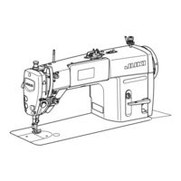
JUKI DDL-9000C-FMS Engineer's Manual (198 pages)
Direct-drive, High-speed, Sewing system with Automatic Thread Trimmer
Brand:
JUKI
| Category:
Sewing Machine
| Size: 14.97 MB
Table of Contents
Electrical Components
8
Caution before Operation
11
Table of Contents
13
Specifications
17
Name of each Component
18
Standard Adjustment
20
Feed Dog Height and Gradient
20
Adjusting the Needle and the Hook
22
Operating Timing of the Feed
24
1)DDL-9000C-F Type
24
2)DDL-9000C-S Type
25
Bobbin Insertion
26
Adjustment of Inner Hook Presser Position
28
Lubrication
30
Method of Lubrication
30
Method of Lubrication to the Oil Tank
32
Method of Oil Drainage from the Oil Tank
32
Cleaning of the Oil Filter
34
Adjusting the Amount of Oil in the Hook
36
Hook Oil Adjustment Procedures
36
Essentials for Hook Oil Adjustments
36
Replacement of the Hook Shaft Oil Wick
36
Various Origin Adjustments
38
Z-Phase Adjustment of a Main Motor
38
Adjustment of the Origin of a Presser Lifter Motor
42
Pitch Motor Adjustment
44
Vertical Feed Motor Adjustment
46
Vertical Feed Link Adjustment
48
Adjustment of Forward Reverse Stitches (Correction Function)
50
Adjustment of Active Tension (Only the DDL-9000C-F)
52
Adjusting the Needle Thread Presser Device
56
Needle Thread Presser Device
56
Adjusting the Remaining Length of Needle Thread
58
Length of Needle Thread Remaining at the Needle
58
Response to Problems Occurring at the Beginning of Sewing
60
Response to Problems Occurring at the Beginning of Sewing
64
Adjusting the Thread Trimming Unit
68
Adjustment of the Thread Trimming Cam Position
68
Adjustment of the Thread Trimming Link Stopper Screw
68
Adjustment of the Thread Trimming Cam Position
70
Adjusting the Knife Unit
72
Adjusting the Knife Unit
74
5)Adjustment of Thread Trimming Speed
74
Adjusting the Knife Unit
75
Adjustment of Rise of the Second Thread Tension Disc
76
Adjustment of the Picker
78
Adjustment of the Driven Part Stopper
80
Adjustment of the Driven Part Stopper
82
Installed Length of the Thread Trimmer Connector Bar (Asm.)
82
Protrusion of the Thread Trimming Shaft and Stopper Position
84
Adjustment of Thrust Values of an Upper Shaft
86
Adjustment of External Parts
88
Adjustment of the Pulley Cover
88
Clearance of the Hand Wheel
88
Adjustment of the Bobbin Winder Unit
90
Control Panel
92
Names and Functions of the Panel Keys
92
Ddl-9000C-S
92
Ddl-9000C-F
93
To Use the Functions of the Serviceperson Level
94
Ddl-9000C-S
94
Ddl-9000C-F
95
External Interface
96
Usb
96
Communication Function
97
How to Use the Communication Function (DDL-9000C-S)
97
How to Use the Communication Function (DDL-9000F-F)
98
List of Communication Data Formats
101
Function of Formatting the USB Device
102
Ddl-9000C-S
102
Ddl-9000C-F
103
Check Program
104
Function of the Check Program(Ddl-9000C-S
104
Use a Check Program Function.(Ddl-9000C-S
105
Function of the Check Program(Ddl-9000C-F
108
Use a Check Program Function.(Ddl-9000C-F
109
Initialization of Data
111
1)Ddl-9000C-S
111
2)Ddl-9000C-F
112
Brightness Adjustment of a Panel
113
Hand Switch Setting
113
Key Customization
114
Assignable Data
114
How to Assign a Function to a Key
115
Setting the Key-Lock and the Password
117
Data List
119
List of Pattern Functions
119
1) Setting Items under the Pattern Sewing Mode
119
Setting Items for the Polygonal-Shape Stitching Steps
120
List of Memory Switch Data
121
Level 1
121
2) Level 2
127
Details of a Memory Switch
130
List of Errors
134
Electrical Component and the Like
138
Construction of a Control Box and How to Remove a Board
138
1) Construction of a Control Box
138
How to Remove the CTL Board Assembly
138
How to Remove the PWR Board Assembly
138
Various Boards
139
1) FLT-T Board Assembly
139
2) FLT-S Board Assembly
139
PWR Board Assembly /PWR -CE Board Assembly
140
CTL Board Assembly /CTL -D Board Assembly
141
INT Board Assembly
142
Optional Input-Output Connector
143
How to Set an Optional Input-Output Function(Ddl-9000C-S
143
How to Set an Optional Input-Output Function(Ddl-9000C-F
146
Position Where an Optional Input-Output Connector Is Placed
147
Maintenance
152
Oil Quantity Check
152
Cleaning
152
Application of Appropriate Grease
154
Needle Bar Lower Bushing and Presser Bar Bushing
154
Feed Bar Mechanism
154
Face Plate Mechanism
156
Inside a Gear Box
158
Application of Appropriate Grease
160
Thread Take-Up Lever Mechanism
162
Replacement of the Motor
164
Replacement of the Timing Belt
164
Replacing the Fuse
166
Changing the Voltage 100V/200V
166
How to Remove a Panel
168
Screws for Attachment and Positions of External Parts
170
Dry Hook
171
Connection Diagram of the Head and Electrical Component
172
Digital Type
172
Full Digital Type
173
Troubles and Corrective Measures
174
Mechanical Components
174
Sewing Performance
179
Drawing of Table
196
Advertisement
Advertisement
Related Products
JUKI DDL-9000C-S Series
JUKI DDL-9000C-F Series
JUKI DDL-9000C Series
JUKI DDL-9000C-SMS
JUKI DDL-9000C-FSH
JUKI DDL-9000C-SSH
JUKI DDL-9000A
JUKI DDL-9000B-SS
JUKI DDL-9000B-MS
JUKI DDL-9000SS
JUKI Categories
Sewing Machine
Industrial Equipment
Sewing Machine Accessories
Accessories
Measuring Instruments
More JUKI Manuals
Login
Sign In
OR
Sign in with Facebook
Sign in with Google
Upload manual
Upload from disk
Upload from URL