Sign In
Upload
Manuals
Brands
Johnson Controls Manuals
Air Conditioner
ZX05
Johnson Controls ZX05 Manuals
Manuals and User Guides for Johnson Controls ZX05. We have
2
Johnson Controls ZX05 manuals available for free PDF download: Installation Manual
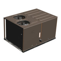
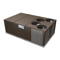
Johnson Controls ZX05 Installation Manual (146 pages)
3-10 ton, 6 ton 60 Hertz R-410A
Brand:
Johnson Controls
| Category:
Air Conditioner
| Size: 14 MB
Table of Contents
Table of Contents
3
General
5
Safety Considerations
5
Renewal Parts
7
Nomenclature
8
Installation
9
Installation Safety Information
9
Preceding Installation
9
Limitations
11
Location
12
Rigging and Handling
13
ZY04-12 Unit Weights
14
Ductwork
23
Duct Covers
23
Condensate Drain
24
Compressors
24
Filters
25
Power and Control Wiring
25
Thermostat Wiring
26
Typical Field Power and Control Wiring
27
Typical Power Wiring
27
High Altitude
28
High Altitude Operation for Non Ultra-Low Nox Units
28
High Altitude Operation for Ultra-Low Nox Units Only
28
Electrical Data
30
ZY04 to 12 Standard Static Indoor Blower - Without Powered Convenience Outlet
30
ZY04 to 12 Standard Indoor Blower - with Powered Convenience Outlet
35
ZY04 to 12 Medium Indoor Blower - Without Powered Convenience Outlet
40
ZY04 to 12 Medium Indoor Blower - with Powered Convenience Outlet
45
ZY04 to 12 High Indoor Blower - Without Powered Convenience Outlet
50
ZY04 to 12 High Indoor Blower - with Powered Convenience Outlet
54
Physical Data
59
ZY04 to ZY12 Physical Data
59
ZXA7 Physical Data
73
Optional Gas Heat
74
Gas Piping
74
Gas Connection
75
Options and Accessories
76
Power Exhaust
77
Blower Phasing
77
Blower Rotation
77
Belt Tension
78
Airflow Performance
81
ZY04 to 12 Side Duct Application (Belt Drive)
82
ZXA7 Side Duct Application (Belt Drive)
86
ZY04 to 06 Side Duct Application (Direct Drive)
87
ZY04 to 12 Bottom Duct Application (Belt Drive)
88
ZXA7 Bottom Duct Application (Belt Drive)
92
ZY04 to 06 Bottom Duct Application (Direct Drive)
93
RPM Selection
94
Indoor Blower Specifications
95
Supply Air Drive Adjustment
96
Everyday Thermostat Control (ETC)
98
Smart Equipment™ Unit Control Board
102
Operation
107
Cooling Sequence of Operation
107
Space Humidity Sensing
109
Reheat Mode Sequence of Operations for Smart Equipment™ Control Only
110
Normal Occupied Operation Mode
110
Normal Cooling Mode
110
Normal Reheat Mode
111
Alternate Mode
112
Flashcodes or Error Messages
113
Smart Equipment™ Economizer Board Details
113
Indoor Air Quality (IAQ)
116
Gas Heating Operation
116
Gas Heat Ignition Control Board Function (Non-Ultra-Low Nox Models Only)
116
Ignition Control Board on Standby
116
Call for Heat
117
Pressure Switch Proving
117
Pre-Purge
117
Ignition Trial Period
117
Flame Stabilization Period
117
Main Burner Operation
117
Post Purge
118
Lockout
118
High Temperature Limit Switch
118
Roll-Out Switch
118
Power Interruptions
118
Flame Present with Gas off
118
Welded Gas Valve Relay Response
118
Gas Heat Ignition Control Board Function (Ultra-Low Nox)
118
Ignition Control Board on Standby
118
Call for Heat
118
Pre-Purge
119
Ignition Trial Period
119
Main Burner Operation
119
Post Purge
119
Ignition Failures
119
High Temperature Limit Switches
119
Burner Inlet Pressure Switch
119
Power Interruptions
119
Flame Present with Gas off
119
Gas Valve Fault
119
Diagnostic Fault Code Storage and Retrieval
120
Cooling Start-Up
120
Pre-Start Checklist
120
Operating Instructions
120
Post Start Checklist
121
Gas Heat Start-Up
121
Pre-Start Checklist
121
Operating Instructions
121
Lighting the Main Burners
121
Shut down
121
Checking Gas Heat Input
121
Two-Stage Gas Heat
121
Manifold Gas Pressure Adjustment
122
Adjustment of Temperature Rise
124
Burners/Orifices Inspection/Servicing (Non-Ultra-Low Nox Models Only)
124
Start up for Units Equipped for Fan Energy Rating
126
Troubleshooting
128
Charging Tables
133
Smart Equipment™ Control Board Navigation Components
139
Start-Up Sheet
140
Advertisement
Johnson Controls ZX05 Installation Manual (88 pages)
Brand:
Johnson Controls
| Category:
Air Conditioner
| Size: 3 MB
Table of Contents
Table of Contents
1
General
2
Installation
5
Preceding Installation
5
Unit Shipping Bracket
5
Condenser Covering
5
Limitations
6
Location
6
ZX04-14 Unit Limitations
6
Rigging and Handling
7
ZX04-14 Unit Weights
8
ZX04-14 Corner Weights
8
Unit 4 Point Load Weight
8
Unit 6 Point Load Weight
8
Center of Gravity
8
ZX04-14 Unit Accessory Weights
9
ZX04-06 Unit Dimensions
10
ZX07 Unit Dimensions
11
ZX08 Unit Dimensions
12
ZX09/12 Unit Dimensions
13
ZX14 Unit Dimensions
14
ZX04-07 Unit Clearances
15
ZX08-14 Unit Clearances
15
1RC0456, 1RC0458 Roof Curb Dimensions
15
Ductwork
16
1RC0457, 1RC0459 Roof Curb Dimensions
16
Condensate Drain
17
Compressors
17
Side Duct Cover Panels
17
Bottom Return Opening for Side Duct Conversion
17
Bottom Supply Opening for Side Duct Conversion
17
Filters
18
Power and Control Wiring
18
Unit Models Used with 1RC0456, 1RC0458 Roof Curb . 15 7 Unit Models Used with 1RC0457, 1RC0459 Roof Curb . 16 8 Control Wire Sizes
19
Electrical Data
20
Physical Data
30
Optional Gas Heat
46
Gas Pipe Sizing - Capacity of Pipe
46
Side Entry Gas Piping
46
Gas Heat Supply Air
47
Flue Exhaust Hood Shipping Location
48
Options/Accessories
49
Standard Economizer and Power Exhaust Set Point
49
Adjustments
49
Blower Phasing
49
Flue Exhaust Hood Installed
49
Supply Air Limitations
50
Belt Adjustment
50
Altitude/Temperature Correction Factors
51
Airflow Performance
52
ZX04-14 Side Duct Application (Belt Drive)
53
High Static Option with Motor Rated at 2.4-Hp
53
Exceeds Recommended Blower Speed
54
Cfm
54
Medium Static Option with Motor Rated at 2.4-Hp
54
ZX04-06 Side Duct Application (Direct Drive)
56
Cfm
56
ZX04-14 Bottom Duct Application (Belt Drive)
57
Available External Static 1.0
57
ZX04-06 Bottom Duct Application (Direct Drive)
60
RPM Selection
61
Indoor Blower Specifications
61
Motor Sheave Datum Diameters
62
ZX04-14 Additional Static Resistance
63
Operation
64
Compressor Operation
64
Intellispeed Supply Fan Control
64
Unit Control Board
64
Economizer Sequences
65
Dry Bulb Changeover
65
Single Enthalpy Changeover
65
Dual Enthalpy Changeover
65
Auto
65
Free Cooling Operation
65
Power Exhaust
66
Setpoints
66
Inputs
66
Outputs
66
Operation
66
Heating Operation
66
Ignition Control Board
66
Gas Heat Board Function
67
Start-Up (Cooling)
68
Start-Up (Gas Heat)
68
Checking Gas Heat Input
69
Gas Rate Cubic Feet Per Hour
70
Gas Heat Stages
71
Typical Flame
71
25 3 Thru 6 Ton, 1/2" Single Stage Gas Valve
72
26 3 Thru 6 Ton, 1/2" Two Stage Gas Valve
72
Troubleshooting
73
27 7.5 Thru 12.5 Ton 3/4" Two Stage Gas Valve
73
Flash Codes for the Gas Heat Ignition Control Board
74
ZX04 Charging Table
76
ZX05 Charging Table
76
ZX06 Charging Table
77
ZX07 Charging Table
77
ZX08 Charging Table System 1
78
ZX08 Charging Table System 2
78
ZX09 Charging Table System 1
79
ZX09 Charging Table System 2
79
ZX12 Charging Table System 1
80
ZX12 Charging Table System 2
81
ZX14 Charging Table System 1
81
ZX14 Charging Table System 2
82
Start-Up Sheet
83
Advertisement
Related Products
Johnson Controls ZX04
Johnson Controls ZX06
Johnson Controls ZX07
Johnson Controls ZX08
Johnson Controls ZX09
Johnson Controls ZXE04
Johnson Controls ZXE05
Johnson Controls ZXE06
Johnson Controls ZXE07
Johnson Controls ZXE12
Johnson Controls Categories
Controller
Air Conditioner
Thermostat
Control Unit
Irrigation System
More Johnson Controls Manuals
Login
Sign In
OR
Sign in with Facebook
Sign in with Google
Upload manual
Upload from disk
Upload from URL