
iWave iW-RainboW-G35D Manuals
Manuals and User Guides for iWave iW-RainboW-G35D. We have 3 iWave iW-RainboW-G35D manuals available for free PDF download: Hardware User's Manual

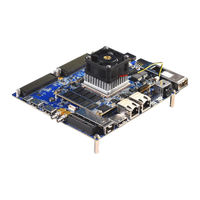
iWave iW-RainboW-G35D Hardware User's Manual (110 pages)
Zynq Ultrascale+ MPSoC (ZU11/17/19EG) SOM Development Platform
Brand: iWave
|
Category: Computer Hardware
|
Size: 7 MB
Table of Contents
Advertisement
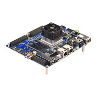
iWave iW-RainboW-G35D Hardware User's Manual (110 pages)
Zynq Ultrascale+ MPSoC (ZU11/17/19EG) SOM Development Platform
Brand: iWave
|
Category: Microcontrollers
|
Size: 7 MB
Table of Contents
iWave iW-RainboW-G35D Hardware User's Manual (102 pages)
Zynq Ultrascale+ MPSoC (ZU11/17/19EG) SOM Development Platform
Brand: iWave
|
Category: Motherboard
|
Size: 6 MB
Table of Contents
Advertisement
Advertisement